
The Poly-Raster Image format
At a glance
| Extension | *.pri |
| Current version |
0.4 (Software & tools; updated on 2020-04-03) 1.0 (Specification of the file format; updated on 2019-05-28). |
| Downloads |
Image converters (source code and binaries). Image loader implementations (commented source code). |
| Documentation |
This page contains the full documentation of the format, plus a
rationale for the design.
The technical description of the file format
is further down on this page. Descriptions of the lay-outs of various displays and controllers are listed in the technical description too. |
Introduction
The Poly-Raster Image format (file extension: ".pri") is a picture file format that holds one or more device-specific bitmaps along with descriptive headers. The Poly-Raster Image format is "yet another" image file format and the first (rhetoric) question to answer, then, is why we need to add another format to the many that exist already?
The goal of the Poly-Raster format is to be a flexible format that is easy to decode, using few resources. In particular, we should not assume that the loader/decoder can keep the entire image in memory. The Poly-Raster format is therefore particularly useful for embedded systems —especially the smallest of these embedded systems.
The display hardware in the "desktop PC" category is quite universal: memory is arranged in "scan lines" with the lowest address in video memory indicating the upper left pixel. Displays for embedded systems are more diverse: for example, for LED sign displays and wide graphic LCDs & VFDs, the display memory is often arranged in columns rather than in rows. Picture files for such displays are often in proprietary formats and only usable on a narrow range of devices. The Poly-Raster Image format brings three advantages over proprietary bitmap formats:
- It saves work. You do not need to write image converters, because these are already available. Image loaders can be ported from existing implementations or adapted from well-commented reference implementations.
- It is easier to support a wider range of displays, since a poly-raster file may hold several bitmaps with different display definitions, resolutions or colour depths.
- It is a documented format, rather than the source code dump that proprietary formats often supply as "documentation" —if any at all. By being described and maintained, the format has a higher chance of survival.
The reasoning behind the Poly-Raster format is that the image loader (on the embedded device) needs to support only a single sub-format. The image encoder, running on a desktop PC, has ample resources to perform the conversion from source image data to Poly-Raster images. In this case, the encoder has to convert the image data to a specific display —if the format does not match the one that the embedded device accepts, the file will simply be rejected. If you wish to make an image that is accepted by several devices, you can ask the encoder to build a multi-bitmap file. Each embedded image loader now chooses the entry that has the format that it supports.
In comparison with flexible and extensible image formats like TIFF, the Poly-Raster format avoids the complexity of parsing various options in order to interpret the pixel data, and the requirement to buffer the image data in RAM if the output device uses a column-ordered or banded lay-out. Instead, the pixel data is present multiple times in a poly-raster file and the loader chooses the most appropriate format. In comparison with "light" formats like WBMP, the Poly-Raster Image format is well-defined. Apart from the description of "sub-type 0" ("scan line" order, monochrome, maximum size 255 × 255 pixels) the WBMP specification essentially tells you that you are completely on your own to define formats for larger images or for a different lay-out of display memory. The WBMP specification, hence, is of no help at all.
File format
A ".pri" file is a collection of bitmaps. There may be only one bitmap in a file, or there may be several. Each bitmap has a header, but there is no "file header" describing the collection of bitmaps. It is up to the implementer or producer of the image to decide which bitmap formats are present in a file (and in what order).
The header of each bitmap gives the details of the format and the pixel lay-out. All multi-byte fields in the header are in Little Endian ("Intel" format). The header itself is 12 bytes in length.
| field | size | description |
|---|---|---|
size | 4 | the number of bytes that the bitmap takes in the file, including the header; if zero, it indicates a file terminator |
id | 2 | a signature, which must be the value A202 (hexadecimal) |
layout | 1 | bitmap type and flags, see the section "Bitmap lay-outs" for details |
depth | 1 | the "colour depth", meaning the number of bits per pixel |
width | 2 | the width of the bitmap in pixels |
height | 2 | the height of the bitmap in pixels |
An image file may contain multiple bitmaps and each bitmap will have a header. This way, a loader may pick the most appropriate bitmap from the file. In fact, most loaders will simply take the first bitmap in the file that they can support, so it is advised to store the highest resolution, most colourful images first in the file.
When browsing through the image file, the loader jumps from one bitmap to the
next using the size field in the header. To see whether the end is reached, a
loader can use the file size. In absence of a file system, e.g. streaming images,
an alternative is to append a terminator to the image —the terminator is a four-byte
field with all four bytes set to 0. When a loader tries to read a new header, the
terminator takes the place of the size field, so a bitmap size of
zero means that no more data will follow.
The bitmap data follows the header (plus an optional extended header) directly,
without any padding. However, if there is a colour map ("palette") in the bitmap,
the colour map precedes the pixel data. The layout field has bits
to indicate the presence of an extended header and/or a colour map. The order
of the data for a single bitmap is thus: header, (extended header),
(colour map), pixel data; where the items between parentheses
are only present if the respective bits in layout field are set.
The extended header is discussed separately in the section on animation.
If present, the colour map holds a number of three-byte entries with RGB components, in the order red-green-blue. The number of entries in the colour map depends on the colour depth: it is 2 for 1-bpp bitmaps, 4 for 2-bpp bitmaps, 16 for 4-bpp bitmaps and 256 for 8-bpp bitmaps; only pictures with 8-bpp or less can have a colour map. When no colour map is present in a bitmap and the colour depth is 8 or less, the bitmap uses a device-specific default palette.
Bitmap lay-out
The layout field defines the lay-out of the pixels in the bitmap.
| bit | description |
|---|---|
| 0 | Column order: if set the pixels are ordered in columns rather than in rows ("scan lines") |
| 1 | Banded lay-out: if set, each byte represents a set of pixels in the opposite lay-out as the general lay-out |
| 2 | Reversed pixel order: if set, bit 0 of the first byte is part of the top left pixel; otherwise bit 7 of the first byte is part of the top left pixel. For RGB images, this flag indicates that the colour order in each pixel is BGR instead of RGB. |
| 3 | Planar: if set, colour or grey level information is arranged in bit-planes overlaying each other. The depth field refers to the bit depth of bit-planes rather than the number of bits-per-pixels. Each plane has a 1-bpp lay-out.
|
| 4 | Inverted Y-axis: if set, coordinate (0,0) is the lower left corner of the display rather than the upper left corner |
| 5 | Extended header present: if set, an extended header is present (immediately after the header) |
| 6 | Colour map present: if set, a colour map is present (it comes after the extended header, or after the header in absence of an extended header) |
| 7 | Loop frame: if set, this image is a loop-back frame at the end of an animated sequence |
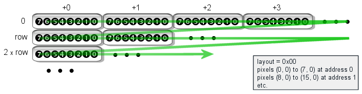
The next few figures give some examples for the bitmap lay-outs. In each case,
the bitmap is a monochrome (1-bpp) picture. The first figure has all bits in the
layout field set to zero. This is a common bitmap lay-out for standard
PC graphics and image file formats; for example, the monochrome BMP and PBM image
file formats use this very lay-out. In the figure, memory address zero is in the
upper left. The address increases by 1 in horizontal order, at at the end of the
row, it wraps back to the left-most byte of the next row. So, for example, if a
monochrome image is 40 pixels wide, eight pixels fit in a byte, a row has (hence)
five bytes and the second row starts at address 5.
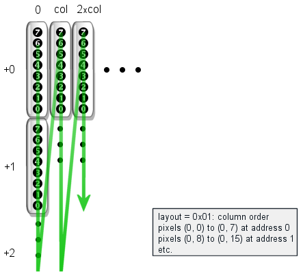
Column order is common for displays and LED signs where data has to scroll horizontally (rather than vertically). You might almost say that a display with column order looks similar to a row-order display that is rotated 90°. In the figure, memory address zero is in the upper left and it increments by 1 for each step in the vertical direction. When arriving at the bottom of the column, the address wraps back to the top of the next column.
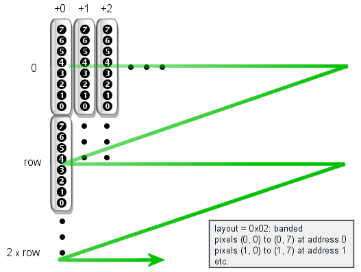
A banded lay-out mixes row and column modes. From a memory addressing perspective, a banded row-order lay-out is indeed row-order: the address increments by one along the horizontal axis. However, a row is now eight pixels high, rather than just one pixel. A banded row-order lay-out is common for dot matrix printers, ink-jet printers and thermal transfer printers.
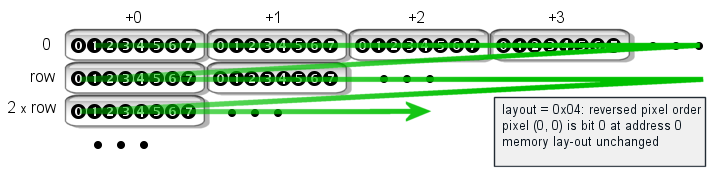
Reversed pixel order only changes the order of the pixels in a byte, in the case
that multiple pixels fit in a byte. Compare the figure below to that of the
layout = 0x00 case.
The bits in the lay-outs may be combined too. I have only presented a lay-out for a banded row-order bitmap, but in similar ways, you can imagine a banded column-order bitmap. For graphic LCDs and OLED displays, banded row-order with reversed pixel order is a common lay-out.
Depending on the number of bits per pixel, some of the lay-out bits are irrelevant.
For example, for an 8-bpp image there is exactly one pixel in a byte and bit 2
in the layout field does not make sense. Similarly, 1-bpp images
are never "planar", as there is only one plane. Only 1-bpp images and planar
images can be "banded". Image writers should clear any irrelevant flags.
The table below lists the lay-outs for a few well-known devices. The "label" column refers to the symbolic name that you can use in the command-line image converter utilities.
| controller | lay-out | label | description |
|---|---|---|---|
| Windows BMP | 0x10 (inverted Y-axis) | bmp | The Microsoft Windows BMP file format uses (0,0) as the left-bottom coordinate. |
| Dot matrix printer | 0x02 (banded rows) | esc_p2 | Most dot-matrix and thermal printers use the ESC/P2 control language originally developed by Epson. The command set is primarily aimed at ASCII text, but it includes commands for graphics. The graphics data must then be sent as banded rows. |
|
Noritake 372 Noritake 900 Noritake 3000 | 0x01 (column order) | gu372 gu900 gu3000 | The Noritake-Itron series 372, 900 and 3000 all use column order for the graphic data. Displays from these series are, for example, the GU256x64-372, the GU256x64-900a and the GU256x64-3900. |
| Noritake 7000 | 0x06( banded rows, reversed pixel order) | gu7000 | The Noritake-Itron 7000 series uses a lay-out similar to that of the KS0107/KS0108 controllers. |
| Noritake 7800 | 0x00 to 0x03 (multiple configuration) | gu7800 | The Noritake-Itron 7800 series has a configurable lay-out for graphic data; it can either use a VGA-compatible "scan line" lay-out (0x00), column-mode, banded mode, and banded column mode. Popular displays from this series are the GU140x32F-7806 and the GU140x16G-7806. |
| KS0107/KS0108 | 0x06 (banded rows, reversed pixel order) | ks0108 | The controller pair KS0107/KS0108 drives a 64×64 pixel area. In a typical set-up, two KS0108 controllers are combined with a single KS0107 controller to form a 128×64 resolution display. |
| SH1101 | 0x06 (banded rows, reversed pixel order) | sh1101 | The SH1101 controller is a compatible alternative to the SSD1305. |
| SSD1305 | 0x06 (banded rows, reversed pixel order) | ssd1305 | The SSD1305 controller drives OLED displays of up to 132×64 pixels. |
| SSD1322 | 0x00 (inverted nibble mode) | ssd1322 | The SSD1322 is an OLED display driver. It allows 16 brightness levels per pixel (4-bit gray scale). It can be configured into several modes. |
| VGA, PC-graphics | 0x00 | vgamono | The most common lay-out for standard PC video cards and bitmap file formats (GIF, PNG, PCX, binary PBM, etc.). |
Pixel encoding
If a bitmap has planes (and assuming a row-encoded bitmap), the file holds in sequence the pixels for layer 0 for a row, then layer 1 for that row, and so forth for the number of planes, before moving on to row 1 (and restarting with layer 0). Column-encoding bitmaps follow the same procedure, but with columns instead of rows.
A row or column (or plane in a row or column) is always padded up to a full byte; no partial bytes are stored. This is only relevant when the number of bits per pixel is less than 8. Other than writing full bytes, no other padding occurs.
Compression
The pixel data of each bitmap is compressed with a simple run-length-encoding algorithm (RLE). The entire block of pixel data is considered to be a single stream of data. That is, compression may span scan lines (or columns). The RLE algorithm compresses "runs" of bytes. For 8-bpp bitmaps, one pixel takes one byte, but for monochrome 1-bpp images, there are 8 pixels in each byte.
The header, extended header and colour table of a bitmap are never compressed.
To expand (i.e. decompress) the pixel data, read a byte from the stream and compare it to the byte previously read. If they are different, just output that byte and safe it as the "previous value" for the next iteration. If the byte read is the same as the previous one, read the next byte from the stream: this is a count byte that says how often the value needs to be repeated.
For the very first byte being read, the "previous value" is assumed to be zero. That is, if the first byte of the pixel data is zero, the second byte is a count that says how many more zeros follow.
The expansion algorithm can be implemented as a read-next-byte routine with only two bytes of status information. See the code snippet below.
struct rlestat {
  unsigned char prev;
  unsigned char count;
};

unsigned char unrle(FILE *fp, struct rlestat *stat)
{
  unsigned char value;
  if (stat->count > 0) {
    stat->count -= 1;
    value = stat->prev;
  } else {
    fread(&value, 1, 1, fp);
    if (value == stat->prev)
      fread(&stat->count, 1, 1, fp);
    else
      stat->prev = value;
  } /* if */
  return value;
}
Before calling the unrle() function for the first time, the fields
of the rlestat structure need to be set to zero. After that, each
call to unrle() returns a single byte (and updates the state
of the decompressor).
Animation with poly-raster images
The poly-raster format allows for simple animations by storing several bitmaps
in a file that all have the same value for the layout field. The
first bitmap is a full and plain image; all other bitmaps have an extended header
that gives the amount of time to wait before putting the next frame on screen,
plus deltas for the horizontal and vertical position of the section of the image
that changes from the previous frame.
The presence of an extended header must be signalled with bit 6 in the layout
field in the standard header. If present, the extended header follows the standard
header immediately. The fields in the extended header are in the following table.
| field | size | description |
|---|---|---|
delay | 2 | the number of milliseconds to wait before displaying this bitmap, relative to the time that the previous bitmap was displayed |
dx | 2 | a value to add to the horizontal position where the pixel is displayed |
dy | 2 | a value to add to the vertical position where the pixel is displayed |
The dx and dy fields allow, in combination with the
width and height fields of the header, to restrict the
stored bitmap to a rectangular area inside the full image. If only part of the
frame changes, only that part needs to be stored in the bitmap of the frame.
The (dx, dy) and (width, height) coordinates are restricted to indicate a byte-aligned
subset of the image. For example, if the image is monochrome (1 bit-per-pixel) and in
row-order, the dx and width are aligned to multiples
of eight pixels. For a column-ordered monochrome image, the dy and
height fields are aligned to eight pixels. For a 2 bits-per-pixel image,
the alignment would be a multiple of four pixels, since four pixels fit a byte in this
case. These alignment restrictions make it easier on the image loader, because no
partial bytes need to be processed.
The delay field indicates the amount of time (in milliseconds) that
should pass before the frame appears on the screen. In other words, it
indicates how long the previous frame should be displayed.
One can, of course, combine animations with multiple lay-outs in a file. The
bitmaps that have the same layout code are part of an animation for
that lay-out. Bitmaps with different layout codes in the same file
are part of animations for a different display.
Image readers that do not support animations read the first (full) image only.
To support animation, an image reader should look for bitmaps with the same
layout code and an extended header further on in the file.
When an animation is a "looping" animation, the last frame should have bit 7 in the
layout field set. This field indicates that the respective frame brings
back the image to be identical to the first (full) image. After the image reader
loads this image, it jumps back to the second frame in the animation.
That is, an image reader decodes the full image, the one without an extended
header, only once, as the very first image.
Miscellaneous notes
When the images are transferred in real-time rather than present in (ROM) memory or on a disk, instead of sending each device every supported format, a server could negotiate which format the client accepts, and send poly-raster files with only the bitmap in that format.
If the image generator were to create an image with bitmaps in every possible lay-out, it would need to include 16 bitmaps for a monochrome image, and more for colour images, especially when the colour image also includes fall-back bitmaps for monochrome displays. In practice, an application or server creates images for a particular group of devices. In this group, some uniformity may be expected. For example, for an application for creating scrolling banners for LED signs may restrict itself to column ordered formats, which are easier to scroll horizontally.
Although a loader may opt to support exactly one bitmap format, it may also choose to do some conversions itself. For example, when a display is laid out in rows (scan lines), it takes only little extra code to supporting an inverted Y-axis in addition to a normal Y-axis. To support both bit orders, you could add a table with reverse byte mapping, which takes 256 bytes of ROM and no RAM.
Software downloads
-
Microsoft Windows: a self-extracting setup that contains the
image converter (both a command-line and a GUI utility), a viewer, source
code examples, and example images. For the converter, the input images must
be in Portable Bit-Map, Portable Gray-Map (PBM & PGM) or the Windows BMP
formats.
 Download
(195 KiB; 2020-04-03)
Download
(195 KiB; 2020-04-03)
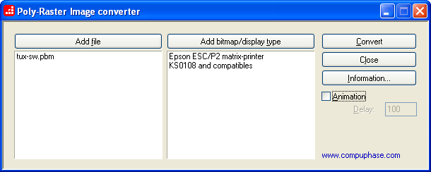
Screen shot of the GUI version of the poly-raster image converter
Image converters (source code)
-
Portable version: converts images to poly-raster format. This
is a command line utility that comes as source code. The input images must be
in Portable Bit-Map, Portable Gray-Map (PBM & PGM) or the Windows BMP formats.
 Download
(40 KiB; 2020-04-03)
Download
(40 KiB; 2020-04-03)
Image loaders
All image loaders come with as code (in C/C++). For Microsoft Windows, also look at the Poly-Raster Viewer, that is included in the self-extracting setup.
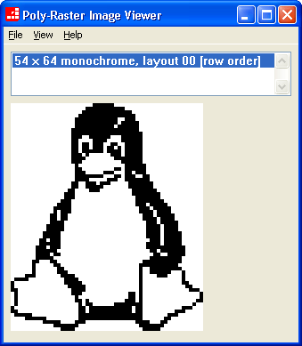
Screen shot of the poly-raster image viewer (image zoomed to 400%)
-
Portable examples in a ZIP archive
The archive contains the source code of a few example implementations for an image loader. A "readme" file in the archive gives details on the implementations. Briefly, one of the examples loads a picture from memory (it could be used to display a bitmap directly from ROM), one reads it byte-for-byte and a third uses a memory cache to speed up loading.
Most of the example implementations write a graphic file in the "Portable Bit-Map" (PBM) format. By changing the output function, you can display the image (rather than convert it). One example shows how to do this by creating simplistic ASCII art from an input image.
Download
(13 KiB; 2020-04-03)
-
Microsoft Windows examples in a ZIP archive
This example loads the matching bitmap entirely in memory before decoding it and then displays the image output in a window. It is a variation of the portable "memory block" implementation (see the archive above). It supports animations in addition to single-frame poly-raster images.
Download
(9.5 KiB; 2020-04-03)
Utilities
- Convert binary file to C source If you want to store an image in the (Flash) ROM of your microcontroller, it is convenient to convert the binary file to C/C++ source code. The image can then be compiled and linked into the binary image of the microcontroller's firmware. I advise the general purpose "xd" utility by John Walker for this.
