
LED current source
The output pins of an interface with TTL logic (such as our programmable MP3 player) can drive a single LED at best. If you must control multiple LEDs with a single output, there are a few options:
-
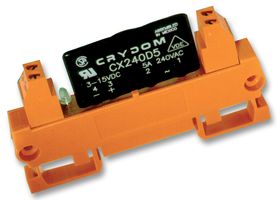 Drive a relay from the TTL logic and switch the LEDs on/off with a separate
power source. This can be convenient if the LEDs already have a current-limiting
resistor. Note that not all relays are compatible with TTL levels. We have used
both DIL relays and solid-state relays successfully.
Drive a relay from the TTL logic and switch the LEDs on/off with a separate
power source. This can be convenient if the LEDs already have a current-limiting
resistor. Note that not all relays are compatible with TTL levels. We have used
both DIL relays and solid-state relays successfully.
- Instead of a relay, use a power transistor. This does not have the overvoltage protection of a relay, but it is cheaper and switches faster. See the article Power-outputs for the H0420 for an example circuit. Again, this circuit is convenient if the LEDs already have a current-limiting resistor.
- To branch two or more plain LEDs, i.e. LEDs do not have a current-limiting resistor, to a TTL output, it is more convenient to use a "constant current source" circuit. This circuit is the focus of this article.
Using a current source is the best way to drive multiple LEDs, because the brightness of a LED depends on the current that flows through it. Even within a series of LEDs (with the same product number and from the same manufacturer), the variation of the forward voltage of the LEDs is quite high. When using a resistor to limit the LED current, the current that flows through the LED is linked immediately to the forward voltage. The variation of the forward voltages of the LEDs, then, leads to differences in brightness.
A current source is immune to the above problem, as it regulates the current, and not the voltage, that flows through the LEDs.
The circuit
The circuit below uses a separate power supply to drive the LEDs. We typically use a 24 V power supply, but any power supply will work. The only factors to consider are that you should not exceed the maximum power dissipation of the transistor.
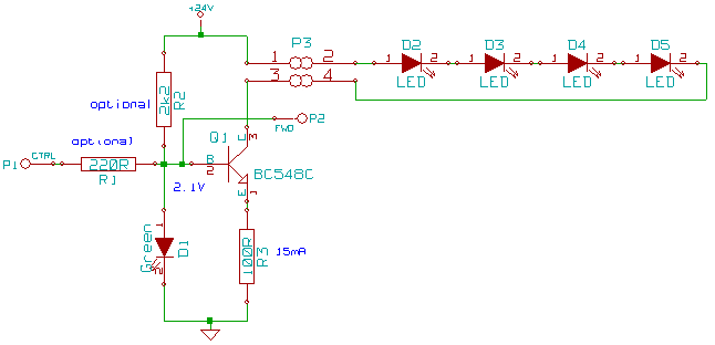
For the circuit, let us first consider that nothing is attached to P1. Then, the base of the transistor and the anode of the LED (D1) are pulled up by resistor R2. Because of the green LED, the voltage at the base of the transistor will be the same as the forward voltage of the LED, which is 2.1 V for a standard green LED. If the base of the transistor is 2.1 V, then its emitter will be 0.6 V lower, or 1.5 V. This means that the current through resistor R3 is 15 mA (1.5 V divided by 100Ω). This same current, then, also runs to the series of LEDs connected between the two pins of P3.
If pin P1 is pulled low, the transistor will block and no current will flow through the LEDs. This capability allows you to switch a sequence of LEDs on and off from an external device, using TTL logic or open-collector outputs. You can dim the LEDs with the same technique: switch the pins off and on in a very quick succession, varying the width of the "on"-pulse. For best results, this pulse-width modulation (PWM) scheme should occur at a frequency between 50 Hz and 100 Hz.
If you plan not to drive the current supply from an external device, you may omit resistor R1 and connectors P1 and P2. Even if you do drive the current supply from another device, you may still omit R1 provided that the external device's output pin is open-collector or has an internal resistor.
Resistor R2 may be omitted if the current supply is driven from an external device (at P1) and that pin is not open-collector. Specifically, for our programmable MP3 player, both R1 and R2 can be omitted.
End notes
The maximum number of LEDs that a single current source can drive at 24 V depends on the colour of the LEDs. Each LED colour is manufactured with different semiconductor material with a different forward voltage. The forward voltages in the table below are approximate, because the typical forward voltage for a LED depends on the manufacturer and even within a series of LEDs, the tolerance of the forward voltage is quite high.
| LED colour | Typical forward voltage | Max. LEDs per current source |
|---|---|---|
| Red | 1.8 V | 10 |
| Super red | 2.2 V | 9 |
| Orange | 2.1 V | 9 |
| Yellow | 2.1 V | 9 |
| Green | 2.1 V | 9 |
| Cyan (aqua-green) | 3.5 V | 6 |
| Blue | 3.6 V | 6 |
| White | 3.5 V | 6 |
This circuit can, at 24 V, drive up to 6 white LEDs and up to 10 red LEDs. If you need to drive more LEDs, you can put several current sources in cascade. To do so, connect pin P2 of one current source to P1 of the next current source.
Similar current sources are available pre-built from Conrad (product number 185027-I5).
