

ICSP programming tool/adapter
This tiny adapter enables In-System Programming of the NXP LPC1000 and LPC2000 microcontroller series using the tag-connect cable and an FTDI TTL-232R-** interface cable. It may also apply to other microcontrollers that use ICSP.
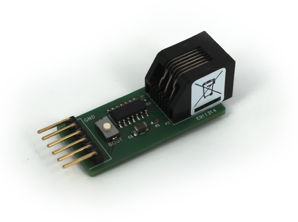
The FTDI TTL-232R or TTL-234X cables (the second is a later design, but both models are perfectly usable) have size wires in a 6-pin, 2.54mm pitch SIL connector. The tag-connect cable has a 6-pin modular jack. The adapter connects one to the other. The only extra trick that the adapter does is that it forces the microcontroller into ICSP mode on a signal of the programming software.
This combination of the FTDI cable, the tag-connect cable and this adapter, is suitable for use with Flash Magic and lpc21isp. Alternatively, you manually put the microcontroller into ICSP state with the tiny pushbutton switch (note: keep the switch pressed for roughly half a second).
For Flash Magic: place a checkmark in the option “Use DTR and RTS to control RST and P0.14” in the “Hardware Config” tab of the “Advanced options”For lpc21isp: include the option “-control” on the command line.
Links for the cables and the software are at the bottom of this page.
Uploading firmware
There are various ways to store program code in the Flash ROM of a microcontroller. Popular are (apparently) JTAG and In-System Programming (ISP). In-System Programming is also called In-Circuit Programming, and (as we do here) In-Circuit Serial Programming (ICSP).
There is the word “apparently” in parentheses in front of JTAG, because I only hear that it is popular, but none of the developers in my circles uses it. Still, it could be wildly popular outside my circles…
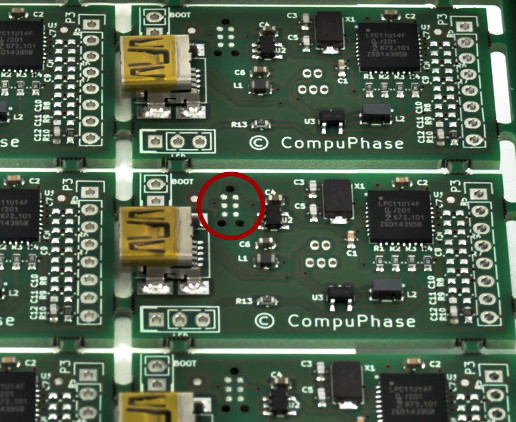
Example of the ICSP footprint for a tag-connect cable (click on the picture to zoom in)
We choose ICSP over JTAG mostly because of the large size of the JTAG connector. Our PCB designs are densely populated; putting a 10x2 pins, 2.54mm pitch header on a PCB that ought to fit in a keyfob is, of course, out of the question.
ICSP needs a connector too. Ideally, one would be able to use a connector that the device already has, for the dual purpose of ICSP too. For example, the LPC1000 and LPC2000 ranges of microcontrollers by NXP use a UART interface for ICSP, so if the device already needs an RS232 port, you may be able use that port for both purposes.
We have settled on the “tag-connect” cables for ICSP on the LPC1000 and LPC2000 series. The required footprint for the tag-connect cable is tiny and you do not need to mount a connector or component —so it is zero cost. If your design has components on only one side, you may choose to put the tag-connect footprint on the other side, to further reduce the space on the PCB that you need to reserve for ICSP.
The tag-connect cable was initially designed for Microchip PIC microcontrollers, and it fits directly into a PICKit 2 or PICKit 3. The Atmel ATMega controllers use ICSP with six lines as well, so an adapter to use tag-connect for ATMega ICSP was quick to appear. Solutions for other microcontrollers followed. None yet for the microcontroller range that we frequently use in our products, however: the NXP LPC1000 and LPC2000.
The LPC series microcontrollers use a (TTL-level) UART for ICSP, plus a “boot” pin that must be held low during reset —and the “reset” pin itself, of course. Add to that the TxD, RxD and ground signals, and it sums up to 5 lines. The sixth pin of the tag-connect cable use to optionally power the device while programming it.
The tag-connect cable must be connected to some kind of programmer or interface; in this case a TTL-level RS232 port. We use the FTDI TTL-232R or TTL-234X cables for it. These cables exists in 5V and 3.3V logic versions. The VCC wire always provides 5V (straight from the USB port that the FTDI cable is connected to), regardless of whether the logic pins are 3.3V or 5V. Since many microcontrollers need to run on 3.3V, the adapter has a slide switch to select between 5V and 3.3V on the tag-connect pin.
To enter ICSP state, you must reset the microcontroller and keep the “boot” pin low while the microcontroller resumes from reset. In their initial “firmware upload” utility, NXP came up with a design where the reset signal was tied to DTR and the boot pin to RTS. The utility would toggle the DTR and RTS pins in the proper sequence, and these would put the microcontroller into ICSP mode. The NXP utility is no longer available and it has been supplanted by third-party tools, but many of them still support the DTR/RTS toggling protocol.
The FTDI cable does not, however, supply a DTR signal; only RTS. To address this, we made an adapter that generates the reset signal from the boot signal, with a monostable multivibrator.
The pushbutton switch on the adapter is a second way to pull down the “boot” and “reset” pins. With the chosen values for R1 and C1, the monostable multivibrator gives a low pulse on the “reset” pin for roughly 0.2 second. This means that a quick press on the pushbutton (i.e. for a shorter time than 0.2s) resets the device, and a long press on the pushbutton puts the device into ICSP mode.
Diagnostics and execution tracing
The communication channel that you use for ICSP can typically also be used at run-time for communicating with a trace viewer or similar. A compact and light-weight trace system (for Microsoft Windows and Linux) was published in “A Trace Tool for Embedded Systems” in Circuit Cellar April 2014 (issue 285).
Links and downloads
- FTDI TTL-232R-3V3 and TTL-232R-5V
- See http://www.ftdichip.com/
- tag-connect
- See http://www.tag-connect.com/
- Flash Magic
- See http://www.flashmagictool.com/
- lpc21isp
- For source, see https://sourceforge.net/projects/lpc21isp/.
For a pre-compiled binary, see: https://github.com/Ladvien/LPC21ISP_Win.
