

Configuring a micro-controller for low-speed USB communication
The faster the data transmission rate, the more critical the cable shielding and the cable length become. A slow transmission rate therefore allows for cheaper and longer cables. Low-speed USB, at 1.5Mb/s, has no problem with cable lengths of up to 5 metres (for longer distances, you can put a hub halfway). This is the main reason why devices that have little data to transfer, will want to use low-speed USB. Devices in the HID class (“human interface device”) are a typical example.
The host (or hub) uses a simple trick to decide whether to communicate with the device in full-speed (12MB/s) or in low-speed (1.5 MB/s). A full-speed device has a pull-up resistor of 1.5kΩ to 3.3V on the D+ line, whereas a low-speed device has the pull-up of 1.5kΩ on the D- line (both the 1.5kΩ and the 3.3V are nominal values). Once the host senses what kind of device is attached, it transmits its packets at the correct frequency.
Toggling the frequency is not the only thing that differs between full-speed and low-speed: the polarity of the differential signal is inverted between the two as well.
Many low-cost USB-enabled micro-controllers make the choice to hardwire the pins for a full-speed USB device. To configure them for low-speed, you “trick” the micro-controller in two steps:
- you divide its clock by 8
- you swap the D+ and D- lines at the USB connector
For example, below is a typical wiring for a full-speed device on a low-cost micro-controller.
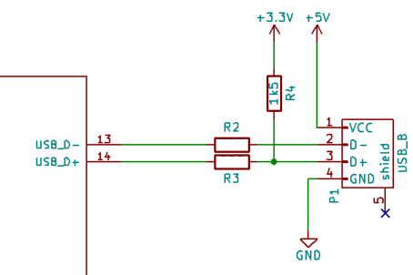
standard wiring (for full speed)
For low-speed, there is only one change: pins 2 and 3 of the USB B connector are swapped. See the image below.
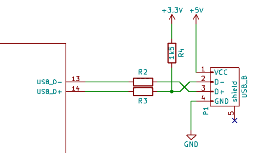
low-speed wiring
To see how it works, consider what happens first on a connection: the host (or hub) sees a pull-up on the D- line and nothing on the D+ line. As a result, the host selects a slow clock and inverts polarity in its communication with the device.
For the micro-controller, nothing has changed: it still sees a pull-up on its USB_D+ pin (the micro-controller might not even test for this). It is logical, then, that the micro-controller expects normal polarity on its USB_D+ and USB_D- pins and at a “normal” clock.
Now, the USB_D+ pin is connected to the D- line (and vice versa), but because the host switched to inverted polarity, the polarity is correct again. The polarity is doubly-swapped, so to speak. To compensate for the lower transmission rate, you only have to make the USB device controller in the micro-controller (or the micro-controller as a whole) run at a slower clock frequency (1/8th of the standard clock frequency —most USB device controllers run at 48MHz internally, so in that case you need to set up an 6MHz clock for USB).
Motivation
From an engineering point of view, this is a clever design to allow device controllers to support both full-speed and low-speed at zero cost. A host must accommodate for both low-speed and full-speed connections, so it must support dynamic protocol switching, but a device is designed for either low-speed or full-speed —not both. That said, if you design a micro-controller with USB support, you want to be able to use it for both low-speed and full-speed devices. This design accomplishes, that when you build a device controller for full-speed USB, it implicitly supports low-speed USB.
… And all that without requiring any extra gates, pins or registers. Even the logic or circuitry to check whether either pin USB_D+ or USB_D- is pulled up, is redundant.
In other words, I think this design was intentional.
I also think, however, that the rationale behind this design has also become “lost knowledge”. Texts on programming USB, such as Jan Axelson's book “USB Complete”, do not mention it, because it is more an electronic layout issue than a programming issue. Data sheets and application notes typically go no further than to mention that the host detects full-speed versus low-speed via the pull-up resistor.
Typical is the following forum exchange:
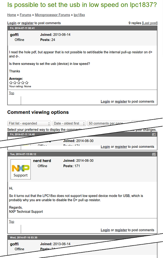
Yes, this is an NXP support engineer talking about an NXP microcontroller. The NXP support engineer would be correct to say that no specific support for low-speed USB is part of the LPC18xx micro-controller design. In fact, only few “device controllers” have explicit support for low-speed operation (for “host controllers”, this is a different matter). The reason is that it is not needed: support for full-speed USB implies support for low-speed USB.
