

Implementing FAT on CompactFlash cards, SD/MMC cards and USB sticks
The goal of this article is to fill in a void in the information needed to implement firmware for a device that reads from CompactFlash cards or SD/MMC cards, such as the programmable MP3-player that we developed. It is very common to put a FAT file system on a Flash card, as doing so makes the card immediately usable by Microsoft Windows and other operating systems. This information also applies to the FAT file system on an USB Flash memory stick, but only partially.
We wrote this document after struggling with FAT16 on a CompactFlash card in the programmable MP3-player based on an MP3 decoder from VLSI Solution and a PIC controller from Microchip. We had two published reference implementations of how to access the CompactFlash card and how to find the start of the FAT and root directory. However, these documents were very terse on what the meaning was of the "magic constants" that were used in data offsets on the card. In addition, although the example source code worked nine out of ten times, it would occasionally "just fail". Further investigation, by us, gave us the reason for the occasional failure and clarified the matter.
Document structure
The first part of the article is a (very) brief overview of FAT. FAT is extensively documented in many books and articles, and detailed specifications are available from Microsoft. The second part is an equally brief overview of the partition table structure. Then, there is a short section on how this applies to embedded devices that do not have a PC-compatible BIOS (or even an Intel 80x86 compatible processor). This document, at its second revision, focuses on FAT16 and FAT32, but it also provides some information on FAT12.
More specific information on the the pin lay-out and CompactFlash card registers (in True IDE mode) and on the pin lay-out and protocols of the SD/MMC cards appears at the end of this document.
This article is, by far, insufficiently detailed to design and develop a fully working CompactFlash reader/writer interface, using FAT. Its purpose is to glue together the various specifications for a single specific purpose. This article may be interpreted as a "guide to the specifications", enhanced with notes from our own experience.
FAT and the Boot Sector
For Microsoft Windows and most other operating systems, a Flash card (in a card reader) and a USB memory stick behave like removable disks. They can be formatted, like a diskette, and they hold a file system. For these devices, the file system is usually either FAT16 or FAT32; the capacity of the virtual disks is usually too large for FAT12 (although SD cards of 64 MiB with FAT12 have been seen in the wild).
In a FAT partition on a hard disk and on a diskette, there is, in this order:
| Diskette regions |
|---|
| a boot sector |
| optionally more reserved sectors |
| FAT #1 (File Allocation Table) |
| FAT #2 (a duplicate of FAT #1) |
| the root directory (not used in FAT32) |
| the "data area" with all files and subdirectories |
All data (files and subdirectories) follow behind the root directory. The sizes of the above parts of the FAT file system are fixed when the disk is formatted. The boot sector is the first sector in a series of reserved sectors. The size of a sector (in bytes) is recorded in the boot sector; it is typically 512 bytes for hard disks. The CompactFlash specification standardizes a sector to 512 bytes.
Historically, there are two FATs, where the first FAT is the leading FAT and the second is a backup in case the first FAT get corrupted. Some storage media may just have a single FAT (having more than two FATs is allowed, but we have never seen such a medium). In the FAT32 system, the second FAT may be leading and the first the copy. The size of the (two) FATs depends on the total size of the disk and on the kind of FAT (FAT12, FAT16 or FAT32). The root directory has a fixed size and can usually hold up to 512 entries (subdirectories can grow and shrink as needed, but the root directory has a fixed size). FAT32 stores its "root" directory in the data area as a standard directory.
A hard disk has partitions and the above lay-out is present at the start of every (FAT) partition. In fact, every partition contains its own boot sector —although it may have a different format and structure for each file system. Details of the partition table and the "master boot record" follow below in a separate section.
To avoid that the operating system has to recalculate this each time, the configuration of the disk is stored at the start of the boot sector. Starting from offset 0x0B (11 decimal) in the boot sector, there is a 51-byte structure that is called the "Disk Parameter Block" (DPB). This block tells you the size of a sector, the number of reserved sectors, the number of FATs (for a FAT operating system) and the size of the root directory.
The first 3 bytes in the boot sector are a "jump instruction" in Intel 80x86 machine code around the Disk Parameter Block. Your microprocessor or microcontroller is likely to be incompatible with the 80x86 instruction set, but you can still use the jump instruction as a kind of signature (note that the FAT specifications allow for two different jump instructions). This is a jump instruction, as the BIOS in a PC (equipped with a 80x86 compatible processor, such as an Intel Pentium), interprets the boot sector as a program that it will load and execute. The 8 bytes following the jump instruction are a vendor name for the disk; this is unrelated to the "volume name" or label of the disk.
The lay-out of the boot sector (with the Disk Parameter Block starting at 0ffset 0x0B) is below. The table shows the fields for the FAT32 structure; the FAT12/FAT16 structures differ from FAT32 starting from offset 0x24. However, the fields at offsets above 0x24 for FAT12 and FAT16 are non-essential: they contain the serial number and volume label, plus values for use by DOS and the BIOS "INT 13" interface, which you probably do not have on an embedded system).
| Offset | Description | Size |
|---|---|---|
| 0x000 | Intel 80x86 jump instruction | 3 |
| 0x003 | OEM name (not the volume name, see offset 0x02B) | 8 |
| 0x00B | Sector size in bytes | 2 |
| 0x00D | Number of sectors per cluster | 1 |
| 0x00E | Reserved sectors (including the boot sector) | 2 |
| 0x010 | Number of FATs | 1 |
| 0x011 | Number of directory entries in the root directory (N.A. for FAT32) | 2 |
| 0x013 | Total number of sectors on the disk/partition, or zero for disks/partitions bigger than 32 MiB (the field at offset 0x020 should then be used) | 2 |
| 0x015 | Media descriptor (bit #2 holds whether the disk is removable) | 1 |
| 0x016 | Number of sectors used for one FAT table (N.A. for FAT32) | 2 |
| 0x018 | Number of sectors per track (cylinder), CHS addressing | 2 |
| 0x01a | Number of heads, CHS addressing | 2 |
| 0x01c | Number of hidden sectors, which is the number of sectors before the boot sector (this field may be set to zero, though) | 4 |
| 0x020 | Total number of sectors on the disk/partition, if this is above 32 MiB (only valid if the field at offset 0x013 is zero) | 4 |
| 0x024 | FAT32 only: Number sectors in the one FAT, replaces the field at offset 0x016 | 4 |
| 0x028 | FAT32 only: Flags for FAT mirroring & active FAT | 2 |
| 0x02a | FAT32 only: File system version number | 2 |
| 0x02c | FAT32 only: Cluster number for the root directory, typically 2 | 4 |
| 0x030 | FAT32 only: Sector number for the FSInfo structure, typically 1 | 2 |
| 0x032 | FAT32 only: Sector number for a backup copy of the boot sector, typically 6 | 2 |
| 0x034 | FAT32 only: Reserved for future expansion | 12 |
| 0x040 | Drive number (this field is at offset 0x024 in FAT12/FAT16) | 1 |
| 0x041 | Current head (internal to DOS; this field is at offset 0x025 in FAT12/FAT16) | 1 |
| 0x042 | Boot signature, the value 0x29 indicates the three next fields are valid (this field is at offset 0x026 in FAT12/FAT16) | 1 |
| 0x043 | Volume ID (serial number; this field is at offset 0x027 in FAT12/FAT16) | 4 |
| 0x047 | Volume label (this field is at offset 0x02b in FAT12/FAT16) | 11 |
| 0x052 | File system type (this field is at offset 0x036 in FAT12/FAT16) | 8 |
| 0x08a | Boot code (starts at offset 0x03e in FAT12/FAT16, and is 448 bytes) | 372 |
| 0x1fe | Boot sector signature, must be 0x55AA | 2 |
It is actually inaccurate to say that a sector is 512 bytes and that the boot sector is the only reserved sector. The sector size and the number of reserved sectors should be looked up from the Disk Parameter Block. In practice, everyone appears to use 512 byte sectors, though. In any case, the boot sector must contain a signature with the value 0x55aa at offset 510 (starting from zero).
When working with the FAT data structure, one confusion to avoid is that between logical and physical sectors. The FAT document refers to a zero-based, linear incrementing, logical sector number. In the geometry of a disk(ette), a physical sector is a pie-like segment; when you use CHS addressing (Cylinder/Head/Sector), you will have to convert from logical sector numbers to physical sector numbers. With CompactFlash cards, SD/MMC cards and USB sticks, you will typically use LBA addressing and you only need to add an offset to the data area to the logical sector.
The Master Boot Record and the partition table
Many USB memory sticks simulate a "big diskette", so with the FAT specifications and the lay-out of the boot sector in hand, we have all the information that we need. On the other hand, CompactFlash cards, most SD/MMC cards and some USB memory sticks mimic a hard disk (or "fixed disk" if you are used to IBM terminology), with a Master Boot Record and a partition table.
For a hard disk (and on a CompactFlash or SD/MMC card), every partition is like a large diskette. A FAT partition has a boot sector, which contains a Disk Parameter Block; it has one or more reserved sectors, two FATs and a root directory. The information about the partitions themselves, however, is in another table, inside another boot record: the Master Boot Record (MBR). The Master Boot Record is also a 512 byte sector. This sector contains a partition table with four entries starting at offset 446 (hex. 0x1BE). Each partition table entry is 16 bytes long. The first 446 bytes typically contain a bootstrap program that the BIOS uses to, well, boot the machine; the last two bytes are a signature and should contain 0x55aa (the same signature as for a standard boot sector).
Initially, disks were addressed with values for the cylinder, the head (platter) and the sector; this is called CHS-addressing (CHS stands for Cylinder/Head/Sector). With a single byte for each of the number of cylinders, the number of heads and the number of sectors per cylinder, the maximum addressable size for a disk is 224, or 16777216 sectors. With a sector size of 512 bytes, the maximum disk size could never exceed 8 GiB (if you look up references on CHS addressing, you will find that the sector and cylinder values are packed together in a single 16-bit word, but for the back-of-the- envelope calculation it comes up with the same result). To accommodate large disks, an alternative addressing scheme was developed: LBA (Logical Block Addressing). This is essentially a linear sector number. Fortunately, the partition table contains the start of the partition and its size in both CHS and in LBA values.
On a CompactFlash or a SD/MMC card, you must therefore first browse through the partition table (which starts at the absolute offset 0x1BE, from the start of the disk) and find the start of the partition. When jumping to the partition, you will then stumble upon a boot record containing a Disk Parameter Block. Then you can proceed to locate and decode the FAT and the root directory, keeping in mind that all offsets in this Disk Parameter Block are relative to the start of the partition.
The table below shows the lay-out of a single record in the partition table. Each such record is 16 bytes in size, and the partition table contains 4 records. That is, the second entry in the partition table starts at offset 0x1CE, the third at 0x1DE and the fourth at 0x1EE.
| Offset | Description | Size |
|---|---|---|
| 0x00 | 0x80 if active (bootable), 0 otherwise | 1 |
| 0x01 | start of the partition in CHS-addressing | 3 |
| 0x04 | type of the partition, see below | 1 |
| 0x05 | end of the partition in CHS-addressing | 3 |
| 0x08 | relative offset to the partition in sectors (LBA) | 4 |
| 0x0C | size of the partition in sectors | 4 |
As the above table shows, the partition table also contains a value that indicates the type of the file system, plus a flag that signals whether the partition is active. A PC will only boot from the active partition. A partition record that is "empty" or invalid typically has all fields set to zero; at least the "type" field of the partition (offset 0x04) should be zero.
A subset of partition type values, related to FAT, is below:
| Partition type | Description |
|---|---|
| 0 | empty / unused |
| 1 | FAT12 |
| 4 | FAT16 for partitions <= 32 MiB |
| 5 | extended partition |
| 6 | FAT16 for partitions > 32 MiB |
| 11 | FAT32 for partitions <= 2 GiB |
| 12 | Same as type 11 (FAT32), but using LBA addressing, which removes size constraints |
| 14 | Same as type 6 (FAT16), but using LBA addressing |
| 15 | Same as type 5, but using LBA addressing |
For "disks" that are on a Flash memory card, Microsoft Windows is very forgiving for the partition type value. Microsoft Windows appears to look at the Disk Parameter Block of the partition itself to determine whether it can support the card. Since CompactFlash cards and SD/MMC cards usually come readily partitioned and formatted (with a single partition for the entire card), this makes sense. Both the SD specifications and MMC specifications even mandate that the file system is a variety of FAT (either FAT12/16 or FAT32, depending on the capacity of the card).
A partition record can also point to an extended partition table (types 5 or 15). An extended partition is a separate partition that holds a kind of "boot sector" that contains a partition table with four more records. Extended partitions are beyond the scope of this paper. Extended partitions almost never appear on Flash memory cards —as said, cards typically contain only a single (primary) partition for the entire card.
FAT & Flash memory cards for an embedded world
After this technical material, the question still remains how this relates to embedded devices using a CompactFlash card for data storage. Very straightforwardly, actually. There is no "magic" involved, but the firmware should adhere closely to the specification of the FAT file system, the Disk Parameter Block and the partition table.
It is important to not make shortcuts when browsing through the partition table. There may be up to four entries in the partition table, but the first partition is not necessarily described in the first entry of the partition table. The firmware should therefore browse through the partition table and skip any invalid entries.
A Flash memory card may contain a small partition for "private use" by an apparatus, that uses a non-standard value for the partition type. If a card has multiple partitions, the firmware should choose the one that has a valid partition type (as the "partition types" table displayed earlier shows, there are three partition type values that are all FAT16; the firmware should expect any of these values, if it is designed to support FAT16). If there is only one partition in the table (with non-zero LBA offset and size), it is best to ignore the "partition type" field in the partition table and get the information from the Disk Parameter Block of that sole partition.
Especially SD/MMC cards have lacking (or invalid) partition type fields, because they are deemed redundant: standard capacity SD or MMC card must use FAT12 or FAT16 and high capacity cards must use FAT32. A bit in an internal register of the SD and MMC cards indicates what kind of card it is: standard or high-capacity.
In any case, what won't work is to have the firmware jump to the absolute byte offset 0x1C6 (word offset 0xE3), read the DWORD at that location and jump to that address plus 1024 to get to the start of the FAT. Such code makes a lot of assumptions:
- it assumes that the Flash memory card contains a Master Boot Record (that said, a brand new CompactFlash card that you buy is usually partitioned and formatted ready for use);
- it assumes that the first partition record is valid —even if a Flash memory card has only a single partition, it could very well be that this partition is described in the second record inside the MBR (we have seen this in practice);
- it assumes that the partition type is what you expect it to be (e.g. FAT16);
- it assumes that there is only one reserved sector (which is common on FAT12 and FAT16, but uncommon on FAT32);
- and if the firmware does not read the Disk Parameter Block, it assumes at lot more...
CompactFlash programming
In most circumstances, it is easiest to program the CompactFlash in "True IDE" mode. This mode simulates the ATAPI-4 interface, but with different timings. The IDE interface is a nearly 1-to-1 mapping to (a subset of) the PC-AT 16-bit expansion bus. In the days of the PC-AT, this design allowed a drive to be connected (almost) directly to the bus. For the sake of compatibility with older hard-disk interfaces (i.e., the Western Digital WD1010 controller), the address decoding in IDE is a little odd, though.
The biggest disadvantage of True IDE mode is that "hot insertion" of the CompactFlash
card may not be supported. The CompactFlash card switches to IDE mode when the
OE / ATASEL line is pulled low at power-up. Several
CompactFlash cards that we tested checked OE pin after a reset and
toggled to True IDE mode when OE is low at reset. Hot insertion worked,
hence, with these CompactFlash cards (when pulsing the RESET line
at drive initialization), but it is not guaranteed to work with all
CompactFlash cards.
We tested CompactFlash cards from SanDisk, Dane-Elec, Integral, Epson and Transcend. The cards by SanDisk, Epson and Integral supported hot insertion after a reset (and switched to True IDE mode after sensing theOE/ATASELline). The cards by Dane-Elec and Transcend did not support hot insertion with a reset, but required a power-cycle to switch to True IDE mode.
We previously reported that Dane-Elec supported hot instertion with True IDE mode, but a recent test failed. We have had reports that the manufacturer had switched to a different "memory controller".
A simple way to get hot insertion to work with True IDE mode is to add a MOSFET in the power line of the CompactFlash card, and to add firmware that detects whether a CompactFlash card is inserted. If it detects this event, it can power-cycle the CompactFlash card. What we often do in our devices is to power-down the CompactFlash card when we detect that it is removed, and to power it up after we detect that it has been inserted.
Some of the signals in IDE mode are active low. In the description of
the signal, this is indicated with a slash in front of the name; for example,
/RESET is the reset signal, and hence to reset the drive this pin must
be pulled to ground. In our description of signals, when referring to an active
signal, the presence of the slash prefix indicates whether the respective pin is
low or high.
The IDE bus is 16-bit. However, internal registers are 8-bit (for backward compatibility),
and reading status or error information returns only 8-bit at a time. The data
bus lines are tri-state if both /CS0 and /CS1 are inactive,
which enables you to use the IDE interface on a bus that also drives other peripherals.
There are lines on the IDE bus that we do not need in an embedded system, but which
were needed for the PC-AT bus. For example, the /IOCS16 signal indicates
whether the output is on all 16 data lines or only on the first 8, but we already
know that data transfers are 16-bit and control transfers (registers)
are 8-bit. In an embedded design, we can leave the /IOCS16 line
unconnected. As an aside, you can switch the CompactFlash card to use only 8-bit
transfers, in case you need to connect the CompactFlash card to an 8-bit bus.
Accessing a drive takes the following steps:
-
The address is asserted on lines
A0-A2and/CS0+/CS1. In True IDE mode, only three of the address lines of the CompactFlash card are used, in combination with the/CS0and/CS1lines which select the "register set". Only either of the/CS0and/CS1lines is active (not both at the same time). -
After a delay of 70 ns (or more), either the
/IORDor/IOWRis activated, depending on whether you want to initiate a read or write instruction. The/IORDor/IOWRare the strobes. -
Another delay, of 165 ns, is needed before inactivating the
/IORDor/IOWRlines. At the same time of inactivating the strobe, or immediately before or after inactivating the strobe, you can read or write the data to theD0-D15lines. -
Although this is optional, it is recommended that both
/CS0and/CS1are inactivated at the end of the read or write cycle. You may need another delay here, because a full cycle has also a minimal duration. Instead of a simple idle loop, you may however choose to perform other operations in that time —such as interpreting the data after a read operation, or fetching new data after a write operation.
The above is a cycle for getting or setting a register in the IDE interface. To access the real data on a CompactFlash card, you need to perform multiple of such cycles to various registers. The unit of transfer is always a sector (and a sector is 512 bytes), but you can read or write multiple sectors in a single command. To get a sector of data, write a "read sector" command (value 0x20) to the Command register after having initialized the four LBA Address registers and the Sector Count registers. Once the command is sent, you will have to wait until the DREQ (Data Request) bit in the Status register comes up. Then 256 read cycles on the Data register will give one sector of data.
| /CS1 | /CS0 | A2 | A1 | A0 | Description |
|---|---|---|---|---|---|
| 1 | 0 | 0 | 0 | 0 | Data |
| 1 | 0 | 0 | 0 | 1 | Error (read) / Features (write) |
| 1 | 0 | 0 | 1 | 0 | Sector Count |
| 1 | 0 | 0 | 1 | 1 | LBA 0-7 |
| 1 | 0 | 1 | 0 | 0 | LBA 8-15 |
| 1 | 0 | 1 | 0 | 1 | LBA 16-23 |
| 1 | 0 | 1 | 1 | 0 | LBA 24-27 + flags |
| 1 | 0 | 1 | 1 | 1 | Status (read) / Command (write) |
| 0 | 1 | 1 | 1 | 0 | Alternate Status (read) / Device Control |
| 0 | 1 | 1 | 1 | 1 | Unused |
The IDE interface defines 10 registers, but the CompactFlash interface does not use the last one. The CompactFlash specification gives the details on the registers (see the resource list at the end of this paper). Note that when the Sector Count register is zero, you are issuing a request to read or write 256 sectors. The "LBA 24-27 + flags" register contains the drive number in bit 4, bit 6 must be set (i.e. non-zero) to select LBA addressing instead of CHS, and bits 7 and 5 are usually set (for compatibility reasons).
Reading a sector is a quick operation, regardless of whether you read sequential sectors or read sectors from random positions. When writing a sector, the operation may either be almost equally quick, or it may take up to 22 ms. When you write sequential sectors, the amortized performance is the one documented in the data sheet. For random writes, the performance can be much lower. The reason for the low performance on random access writes is that a write operation on Flash memory can only write 0 bits. To write a 1 bit, the Flash memory must be "erased". An erase operation sets all bits to 1 in a "Flash sector", and a Flash sector is typically much larger than the 512 bytes of a FAT sector (sorry for the confusion, but it so happens that both quantities are called "sectors").
Suppose you write one FAT sector at a random location. That sector must first be erased (to all 1's), because Flash memory can only program 0's. But erasing the Flash sector also erases all other FAT sectors in it. These may not be lost, and therefore they must be copied to a scratch area before the erasure, and be copied back after erasure. The actual procedure is a little more intelligent than this (using remapping strategies), but the point is that a single write operation can cause a chain of events that, together, cause a huge performance degradation. For details, you may look at the Microsoft Technical Report "A Design for High-Performance Flash Disks", see the References section and the end of this document.
The table below contains the wiring from CompactFlash to an IDE interface. Note that we describe only the signals that are needed for the CompactFlash card —if you want to build an adapter for CompactFlash that plugs into an IDE connector of your PC, connect pins 2, 19, 22, 24, 26, 30 and 40 to the ground, connect pin 28 to Vcc via a 10k resistor and leave pins 20, 21, 29 and 32 unconnected.
| CF pin | IDE pin | Dir. | Description |
|---|---|---|---|
| 1 | gnd | - | ground |
| 2 | 11 | I/O | D3 |
| 3 | 9 | I/O | D4 |
| 4 | 7 | I/O | D5 |
| 5 | 5 | I/O | D6 |
| 6 | 3 | I/O | D7 |
| 7 | 37 | I | /CS0 |
| 8 | gnd | I | A10 |
| 9 | gnd | I | /OE (/ATASEL), pull low for True IDE |
| 10 | gnd | I | A9 |
| 11 | gnd | I | A8 |
| 12 | gnd | I | A7 |
| 13 | Vcc | - | Vcc (3.3 V or 5 V) |
| 14 | gnd | I | A6 |
| 15 | gnd | I | A5 |
| 16 | gnd | I | A4 |
| 17 | gnd | I | A3 |
| 18 | 36 | I | A2 |
| 19 | 33 | I | A1 |
| 20 | 35 | I | A0 |
| 21 | 17 | I/O | D0 |
| 22 | 15 | I/O | D1 |
| 23 | 13 | I/O | D2 |
| 24 | N.C. | O | /IOCS16 |
| 25 | - | I | /CD2 (Card Detect; no IDE equivalent) |
| 26 | - | I | /CD1 (Card Detect; no IDE equivalent) |
| 27 | 10 | I/O | D11 |
| 28 | 12 | I/O | D12 |
| 29 | 14 | I/O | D13 |
| 30 | 16 | I/O | D14 |
| 31 | 18 | I/O | D15 |
| 32 | 38 | I | /CS1 |
| 33 | N.C. | O | /VS1 |
| 34 | 25 | I | /IORD |
| 35 | 23 | I | /IOWR |
| 36 | Vcc | I | /WE |
| 37 | 31 | O | INTRQ |
| 38 | Vcc | - | Vcc (3.3 V or 5 V) |
| 39 | gnd | I | /CSEL |
| 40 | N.C. | O | /VS2 |
| 41 | 1 | I | /RESET |
| 42 | 27 | O | IORDY |
| 43 | N.C. | O | reserved |
| 44 | Vcc | I | reserved, pull high for True IDE |
| 45 | 39 | I/O | /DASP |
| 46 | 34 | I/O | /PDIAG |
| 47 | 4 | I/O | D8 |
| 48 | 6 | I/O | D9 |
| 49 | 8 | I/O | D10 |
| 50 | gnd | - | ground |
When the CompactFlash card is in another mode than True IDE, the names of the pins (and their functions) are different from the descriptions in the above table.
The above table is assuming an 40-pin IDE connector. The table below lists the meaning of the pins 41 to 44 for a 44-pin connector (commonly found in notebook computers). A 44-pin IDE connector includes power lines (+5V). A CompactFlash card is designed to run at two voltages: 3.3 V (±5%) or 5 V (±10%), but not both at the time. See the specification for details.
| IDE pin | Dir. | Description |
|---|---|---|
| 41 | - | +5V for the logic |
| 42 | - | +5V for the drive motor |
| 43 | - | gnd |
| 44 | I | Controller type, 0 = ATA (leave unconnected) |
In your design, you may choose to omit a few lines. For example, the support for
the IORDY signal is optional in the CompactFlash specification
and you could choose to not use the signal at all (rather than trying to detect whether
it is supported). The /IOCS16 signal does not convey any information
that you did not already know, so that pin may be left unconnected as well. You may
take such a decision for the pins /PDIAG and /DASP, and
perhaps for /CD1, /CD2, INTRQ and /RESET
as well.
As always, there are the difficulties of handling CompactFlash cards that do not follow the standard strictly. We have encountered CompactFlash cards that identify themselves hard disks, rather than returning the signature specified by the CompactFlash document. Also, the timing and sequence diagrams for various status signals are sometimes not adhered to. Unfortunately, there is no other option than to test with as many different CompactFlash cards as possible.
SD/MMC card programming
The specifications for SD cards and MMC cards come at a price, while they are free for CompactFlash cards. Furthermore, the specifications for SD cards and for MMC cards are controlled by two different organizations: the SD Card Association and the MultiMediaCard Association. These look at each others work, with the goal of remaining compatible if possible, but incompatibilities exist.
For MMC, there are two different serial interfaces to talk to the card: the standard interface SPI and a custom interface (that would allow multiple cards on one serial interface bus). The SD card adds a third protocol where four bits are transferred in parallel. Most "open source" code for interfacing SD/MMC cards use SPI mode. (The newer MMCplus and MMCmobile cards also allow 4-bit and even 8-bit parallel transfers.)
Regardless of the interface, the protocol used for both SD and MMC is based on transactions where the host initiates a transfer by sending a command and the card responds with status information, the actual data and a CRC. The card must remain selected (the "chip-select" signal must remain asserted) for the entire transaction and the host must be able to process the reply within the timings mandated by the serial interface.
The bulk of the commands are known because of the publicly available, detailed
datasheets of Samsung (a manufacturer of MMC cards). The commands are known by
both index number and by nmemonic name. For example, the command to select the
card for a subsequent read data or write data operation is simultaneously known
as SELECT CARD and as CMD7.
To read a particular FAT sector, one must first set the start address to read from (the number of bytes the read must also be set; for a FAT sector this always is 512 bytes). Here is a catch: on the standard SD and MMC cards, the address is in bytes, so if you pass in a (physical) sector number, you must multiply the sector number by 512 to get the address. With the newer "high capacity" cards, the address is in multiples of 512 bytes —the address is the same as sector number. This means that the host must detect whether the card is a high capacity card or a standard card. This is also an area where the SD and the MMC specifications are incompatible, meaning that you first have to detect whether a card is an SD card or an MMC card.
Testing for SD versus MMC is typically done by sending a command to the card that
exists in the SD specification and is not present in MMC cards. The command to
use for this is APP OPERATING CONDITION or CMD41. An
MMC card will just time out on this command (and not respond). This command also
returns the "Operating Configuration Register" (OCR), which contains the "high
capacity" bit. This bit is only valid if you requested that it be set in CMD41.
However, before you can request this bit, you must first have sent the command
SEND INTERFACE COND to the card (CMD8); otherwise an
old SD card (with standard capacity) will return "busy" on the subsequent CMD41 with
the request for the "high capacity bit". The high capacity bit is bit 30 in the OCR.
Even with this precaution (setting the "high capacity bit" in the
SEND INTERFACE COND command), command
APP OPERATING CONDITION may return with the
status that the card is not ready. The command should then be repeated. For some cards,
it can take a while to reach "ready" state; we advise to keep repeating the command for at
least 0.2 seconds before giving up.
So the procedure is: check whether the SD card supports version 2 of the SD specification (which is the first to define the high capacity bit) with CMD8, then test for the bit with CMD41. If the card does not support version 2 of the SD specification, you still issue CMD41, but without requesting for the high capacity bit), to differentiate between a standard capacity SD card and an MMC card.
When the card is confirmed to be an MMC card, with the above procedure, you can
issue SEND OPERATING CONDITION (CMD1), which is the
MMC equivalent of CMD41. This command also returns the OCR, and like CMD41, it
also returns the "high density" bit if it was requested. In fact, the MMC
specification (version 4.2) defines two bits in the OCR for the access mode,
bits 29 and 30, where SD only has a single bit. For standard capacity cards, both
these bits are 0; for high capacity cards, bit 29 is zero and bit 30 is 1. Older
MMC cards (that do not support the request for the access mode) may return 0:0
or 1:1 in bits 30:29, which are both interpreted as "standard capacity", or they
may time out on the command, in which case the host resends CMD1 without the
request for the access mode.
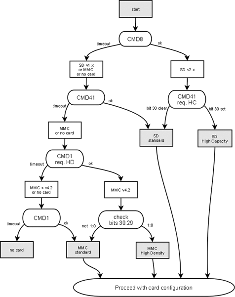
The flow chart illustrates the procedure. In program code, you may remove some redundancy in the flow chart. For example, after CMD8, the next command is always CMD41 —only the argument to the command is different. Similarly, the repeated call to CMD1 might be implemented as a loop, with the "access mode" request cleared from the argument on the second iteration.
Standard capacity cards typically use FAT12 or FAT16, because the SD and MMC specifications mandate them. Microsoft disadvises FAT12 for disks with capacities above 4 MiB and declares the upper limit of FAT12 disk capacity at 32 MiB. Yet, SD/MMC cards with capacities of 64 MB or more that use FAT12 exist and are not as rare as one may assume. This is because the SD and MMC specifications use a minor modification of the old FAT12 specification: it stores the "total number of sectors in the partition" as a 32-bit field at offset 0x020 in the Disk Parameter Block, instead of the 16-bit field at offset 0x013. The 32-bit field at offset 0x020 did not exist in the original specification of FAT12. With this trick, the maximum size of a FAT12 partition is boosted from 32 MiB to roughly 256 MiB (maximum cluster size of 64 KiB multiplied by 4085, which is the maximum number of clusters that FAT12 can support). To better support FAT12, the SD Card Association even provides it's own formatting utility, presumably because the standard format utility of current operation systems will refuse to format cards over 32 MB with FAT12.
The "SD Memory Card Formatting Software Instruction Manual" makes the following claim:
"Generally, SD/SDHC Memory Card file systems formatted with generic operating system formatting software do not comply with the SD Memory Card Specification."See the references section (below) for a link to the SD Memory Card format utility.
References
- CompactFlash Association; CF+ and CompactFlash specification, Revision 2.0; 2003.
- The full specification: electrical, physical and software interface. Especially the sections about the timing and the register descriptions are relevant in relation to this article. Downloading the latest specification requires a free registration.
- LakeView Research; The Mass Storage Page.
- An article and resource list on/for mass storage devices that connect on the USB port, such as memory sticks and (CompactFlash) card readers/writers.
- Birrell, A., M. Isard, C. Thacker, T. Wobber; A Design for High-Performance Flash Disks; Microsoft Research Technical Report MSR-TR-2005-176; December 2005.
- The first 3 pages of this techical report present measurements and an analysis of random writes on a CompactFlash card.
- SD Card Association; Simplified SD Specifications - Part 1, Physical Layer, Version 2.00; September 2006.
- The simplified specifications for the SD cards can be obtained through this link (after accepting a license agreement) at no cost. The simplified specifications cover standard SD cards and high capacity SD cards.
- Matsushita Electric Industrial Co., Ltd. (Panasonic); SD Memory Card Formatting Software version 2.0; September 2006.
- The "SDFormatter" utility, its manual and a FAQ can be downloaded from this page.
- Samsung Electronics (Product Planning & Application Engineering Team); High Density MMC Application Note; May 2006.
- Presentation handouts discussing version 4.2 of the MMC specifications. This revision of the specification introduces "high density" cards, that can exceed 4 GB. The document compares high density MMC cards with high capacity SD cards.
- Microsoft Hardware White Paper; FAT: General Overview of On-Disk Format; Microsoft Corporation.
- Technical information about FAT (FAT12, FAT16 and FAT32). I dislike the writing style and there are a few typographical errors, but the technical information is accurate and fairly complete. This is a link to a PDF file.
- Technical Committee T13; Information Technology -AT Attachment with Packet Interface Extension (ATA/ATAPI-4); August 1998.
- The link is to a working draft of the specification of the ATA-IDE interface, in PDF format. (The printed final documents cab be ordered from ANSI).
- Villani, P.; "The FreeDOS Kernel"; R&D Books; 1996; ISBN 0-87930-436-7.
- A good introduction to FAT12 and FAT16, but the criterion to choose between FAT12 or FAT16 looks suspicious. The description of FAT32 is lacking.
- m VFAT Long File Names.
- A brief technical document on how long filenames are implemented on the FAT file systems.
