

Connecting a bar-code wand to the MP3 controller/player
Barcode readers/scanners typically provide interfaces for keyboard emulation, the RS232 port and, more recently, the USB port. Some offer wand emulation, which is a pulse train on a single output pin of a special connector (typically not found on a PC, but software exists to link such wand emulation readers to the parallel port).
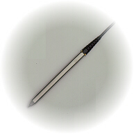
Obviously, the electronics of these interfaces add to the price of the bar-code reader. The RS232 interface furthermore requires external power. A low cost option, is to use a bar-code wand —a pen-style reader. If the H0420 MP3 controller is programmed to understand the pulse train produced by a wand, no decoder or emulation interface is needed. Such "undecoded" wands are in the price range of $50.= to $100.= for rugged, steel-housed pens; a fraction of the price of a CCD or a LASER scanner. Indeed, these bar-code wands can be produced so cheaply that they have been distributed for free with magazines (the ":CueCat" by Digital Convergence).
Connecting the bar-code wand
A typical bar-code wand has only three wires: power, ground and data (output). All undecoded wands use TTL-level outputs (the classifications "undecoded" and "TTL interface" are used interchangeably). A typical bar-code wand uses less than 10 mA of power, and therefore they can be fed by a digital output of the H0420. This set-up allows the bar-code wand to be switched on and off under control of the H0420 MP3 controller.
The configuration that I will use for this article is to use pin 10 of connector block J7 for power (this is I/O line 15) and pin 8 of J7 for the data (I-O line 14). For the ground, I have the choice of pins 7 or 9 of connector block J7 —I usually choose pin 9.
| Connector block J7 | |
|---|---|
| pin | usage |
| 8 | data |
| 9 | ground |
| 10 | power (5V) |
There is no standard for the connector and the pin-out of the bar-code wand. Especially the older bar-code wands use 5-pin DIN connectors, with the pin-out in the figure below:
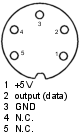
On a few bar-code wands, the DIN connector was replaced with a mini-DIN plug, but with the same pin-out. Other bar-code wands use a 9 pin D-style connector. In these cases, the pin-out can often be found in the datasheet of the wand.
The TTL output is almost always open-collector output. Therefore, a 4k7 pull-up resistor between the "power" and "data" pins should be added on the hardware side; I typically solder it on the connector for the bar-code wand. Even if a particular bar-code is not open-collector, this 4k7 resistor does not hurt.

Connection diagram for a DataLogic P51 undecoded TTL barcode wand to the H0420 programmable MP3 controller/player;
HP barcode wands typically use the pin-out: 2=data, 7=ground, 9=power (5V) on the D-styke connector
Detecting bars
The hardware requirements are minimal: a connector and a pull-up resistor (plus the bar-code wand itself). All the intelligence happens on the software side. The first steps are to declare I/O line 15 as "output" and set it high, so that the bar-code wand receives 5V power, and to declare I/O line 14 as "sampling" in order to receive high-resolution timestamps related to TTL-level changes.
After receiving a burst of samples, the relative time differences (that you receive with the samples) indicate the relative width of the black bars and the wide gaps between the bars. See the paper on receiving commands from an infrared remote control for a detailed discussion on receiving sampled data. The time delta for a bar or gap depends on the speed with which you move the wand over the bar-code: move the wand quickly over the bar-code and you get small time deltas in the received samples, move it slowly and you receive large time deltas. As a result, to decide whether a bar (or gap) is a wide one or a narrow one, you need to "normalize" the time deltas.
Most bar-code lay-outs have a leader and a trailer, which serve for error checking but which can also be used for getting an estimate on the velocity of the wand swiping over the bar-code. Since most lay-outs also use different bar-code patterns for the leader and the trailer, you can also use the leader and the trailer to detect the direction of the swipe: left-to-right or right-to-left. My current software does not take the direction into account; it only supports left-to-right scans (unless you print the bar-codes as a mirrored image, of course).
You can download a working example (source code
in the pawn language) that decodes 4 and 6 digit bar-codes in the "interleaved
2 of 5 symbology". The sample script implements the function barcode_init(),
which handles typical configuration and sets up the function barcode()
to receive any decoded bar-code values. Function barcode() is one that
you have to write yourself, it may look like the example below. Here, the function
barcode() makes a filename from the code (code 137 results in filename
"track137.mp3") and plays it. You can add special codes for volume up/down.
#include <barcode>

main()
    {
    /* initialize the wand */
    barcode_init .sample_pin = 14, .power_pin = 15
    }

barcode(code)
    {
    new str[20 char]
    strformat str, _, true, !"track%d.mp3", code

    if (fexist(str))
        play str
    else if (audiostatus() == Stopped)
        play !"failure.mp3"   /* track for this code does not exist */
    }
When there is a barcode read error, the function barcode() receives
code set to -1. You may want to explicitly check for this code. The above example
function will attempt to play the file "track-1.mp3" on an error, and play the
track "failure.mp3" if there is no such track.
If you want to see how decoding is done technically, look at the file "barcode.inc" in the ZIP archive. This file contains commented source code. For the details of the "interleaved 2 of 5" symbology, see below.
Code: Interleaved 2 of 5
Many bar-code symbologies exist, see the Wikipedia article on bar-codes for a list. The EAN13, UPC-A and ISBN symbologies are well known, because they are used in retail and on books. Other bar-code symbologies are specialized or more appropriate for special environments.
For the example program presented in this article, I have selected "interleaved 2 of 5" because it is a simple, compact and reliable encoding. As the name says, this is an encoding in which the bars & gaps for a digit are interleaved with those of another digit. More specifically, the symbology encodes pairs of digits and it uses five bars (with five gaps between the bars) for each pair. The bars give the bits for the first digit of a pair and the gaps are the binary bits for the second digit of the pair. Interleaved 2 of 5 is also called the "ITF symbology", by the way.
There are two sizes of bars and of gaps: narrow and wide. The wide bar/gap should be at least twice as wide as a narrow bar/gap. A wide bar/gap stands for a binary 1 and a narrow bar/gap is zero. The fifth bar and gap of each interleaved pair is a kind of check bit (or "parity bit"), the remaining four are used in a weighted BCD scheme. The interleaved 2 of 5 symbology can only encode an even number of digits. If you encounter an interleaved 2 of 5 barcode with an odd number of digits, the last digit is simply not shown, but it is present (the last digit may be used as a checksum value over the entire code).
In a normal BCD scheme, the values of the bits contribute to the end value in powers of two. The first bit, if set, contributes 1 (20), the second bit 2, the third bit 4 and the fourth bit 8 (23). So the bit pattern 1-0-1-0 (or the bar pattern "wide-narrow-wide-narrow") stands for the decimal value 5: the first and third bits are 1 and therefore the result is 1+4. The interleaved 2 of 5 symbology deviates from BCD by making the fourth bit contribute 7 to the result, not 8.
Using powers of two for the contributed values of bits guarantees that any number has exactly one bit pattern that encodes it. When the fourth bit has the value 7, both the bit patterns 1-1-1-0 and 0-0-0-1 would result in the number 7. Interleaved 2 of 5 avoids ambiguity by further mandating that there are exactly two wide bars (and exactly 2 wide gaps) in each series of 5. This means that the bit pattern 1-1-1-0 is invalid, because it would require three wide bars/gaps. The second pattern, 0-0-0-1 is valid, provided that the check bit (the fifth bar/gap) is also 1.
| first 4 bits | 5th bit | decimal value | |||
|---|---|---|---|---|---|
| 0 | 0 | 1 | 1 | 0 | 0 |
| 1 | 0 | 0 | 0 | 1 | 1 |
| 0 | 1 | 0 | 0 | 1 | 2 |
| 1 | 1 | 0 | 0 | 0 | 3 |
| 0 | 0 | 1 | 0 | 1 | 4 |
| 1 | 0 | 1 | 0 | 0 | 5 |
| 0 | 1 | 1 | 0 | 0 | 6 |
| 0 | 0 | 0 | 1 | 1 | 7 |
| 1 | 0 | 0 | 1 | 0 | 8 |
| 0 | 1 | 0 | 1 | 0 | 9 |
The table above shows the bit patterns for the ten digits. As is apparent, digit zero is an exception: it is actualy encoded as 11. The fifth bit is chosen so that the number of bits in a five-bit series is two: 2 wide bars in each series of five and two wide gaps in each series of 5.
Every barcode in the interleaved 2 of 5 symbology starts with a leader code and it ends with a trailer code. The leader code is a sequence with four narrow elements, so: "narrow bar - narrow gap - narrow bar - narrow gap". The trailer code is a wide bar followed by a narrow gap and a narrow bar. The figure below shows a bar-code that encodes the value 1234. The left and right margins in blue indicate the leader and the trailer; on a true bar-code these would be black & white just like the rest of the bars and gaps.

Bar-code with the value 1234 in the interleaved 2 of 5 symbology
Special applications
The advantage of doing your own bar-code decoding is that you can invent your own bar-code symbology. In some applications, using a uniquely different symbology may provide a bit of extra robustness in scanning tickets, plus that it makes it a little harder for a (malliscious) user to print his or her own (false) tickets. What interests me in particular is to create a more compact version of the interleaved 2 of 5 symbology. As we have seen, interleaved 2 of 5 uses 5 bars and 5 gaps to encode two decimal digits, with a check bit for each digit. This could be extended (and actually symplified) by encoding two hexadecimal digits in these 5 bar/gap pairs. When you combine the two check bits to form a single 2-bit number, you catch more errors than just a single parity bit per digit. Six hexadecimal digits give you a range of 16,777,216 unique values compared to 1,000,000 values for six decimal digits.
Bar-code wands are almost a thing of the past, but there exists a modern variant that also uses an undecoded TTL interface: the bar-code slot scanner. Slot scanners are robust, because they are table-mount or wall-mount and because the sensitive opto-electronics are shielded by the enclosure. One operates such slot scanners in the same way as with the better known magnetic-strip card readers. An advantage of a bar-code slot reader is that a ticket with a bar-code is a lot cheaper to produce than a plastic card with a magnetic strip. Therefore, the bar-code readers are better suited for single use (or short-term use) tickets.
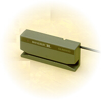
The DataLogic DLS2000 slot scanner
Further reading & references
- H0420 Programmable MP3 Player
- The main page for the MP3 player that this article applies to.
