

Mini-tray for SMD components
The mini-tray was designed as an alternative to the standard JEDEC tray for semiconductors. It has the same width as a JEDEC tray, but its length is a third of that of a JEDEC tray. Thus, three mini-trays lined up have the same width/length dimensions as one standard JEDEC tray (the mini-tray is 0.85 mm thinner than a JEDEC tray).
-
-
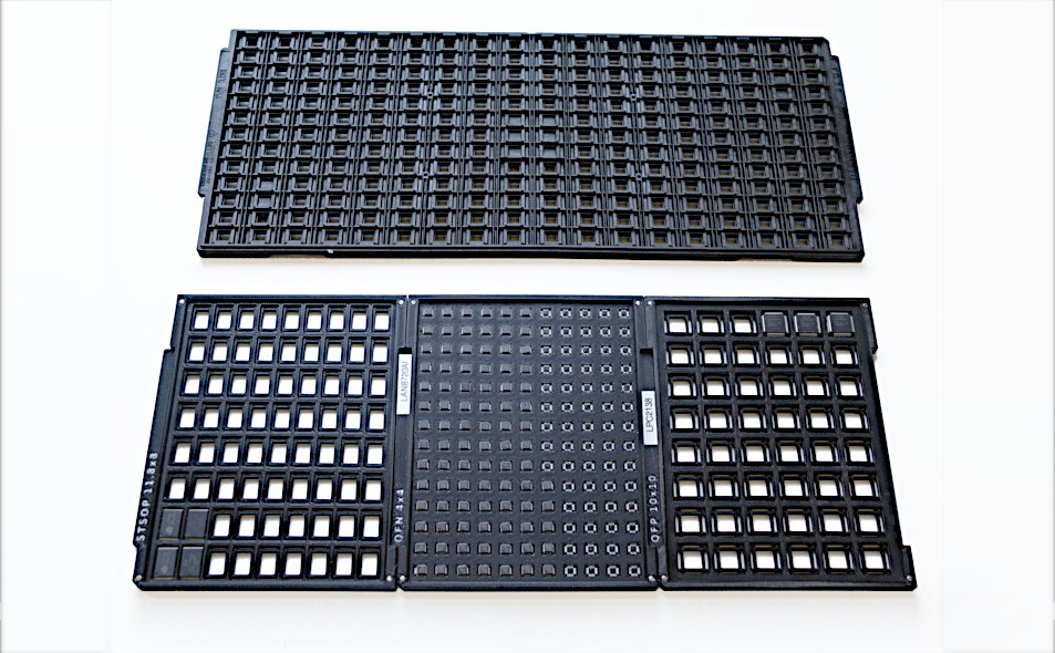
mini-trays compared to JEDEC tray
-
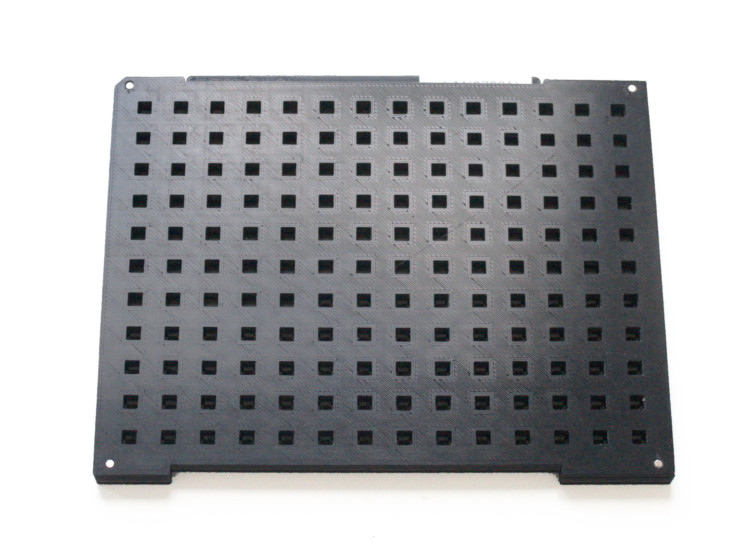
mini-tray with lid/cover
The design of the mini-tray aims at small-scale production and storage of small series of components. Small pick-&-place have limited space for trays, sometimes only a single one. Mini-trays then allow for three times as many different tray-packaged components in a single project.
With the standard JEDEC tray, an empty tray (for the same component package) serves as a lid for a full tray. The rationale is that for mass production, you put a stack up to 20 full trays in the pick-&-place machine. In this stack, each full tray is the lid for the tray below it. The large pick-&-place machines have a robotic arm with suction cups to automatically lift and remove an empty tray from the top of the stack. In this context, using an empty tray as a lid for the stack is a straightforward solution.
There is no pick-&-place machine that can unstack mini-trays, though, and it is unlikely there will ever be one. Therefore, the mini-tray design includes a dedicated lid (or “cover”). An additional advantage of a dedicated lid is that it does not obscure the tab of the tray: this tab is where you will put a label with the part label or description.
The mini-tray is also designed to have a magnet in each of the four corners, so that the lid snaps on the tray (and the mini-trays snap together). There is thus less risk that the components can “wiggle” out of their pockets while you are handling a tray (with its lid on). For storage, it is still recommended to also add a rubber band around a mini-tray with lid.
The relatively small size and the more common width/height ratio of the mini-tray makes it fit well in standard 127 mm × 152 mm anti-static sealed bags, together with a small bag with silica gel. These bags are available with grip-lock closing, and so they are reusable.
Like the JEDEC trays, mini-trays have a chamfered corner to indicate orientation. The step sizes (from pocket to pocket) in the horizontal and vertical direction are also copied from JEDEC trays (with four exceptions, see the table below).
The body size in the table excludes the pins; it is the nominal size of the body as given in the datasheet for the component. In practice, pins for TQFP, LPQFP and other members of the QFP family, are 1 mm long.
| Type | Body size | Thickness | Columns | Rows | X-step | Y-step | JEDEC reference |
|---|---|---|---|---|---|---|---|
| (T)QFP | 5×5 | 0.5 ~ 1.7 | 12 | 9 | 10.50 | 10.10 | CS-004/AG, CS-007/AA |
| (T)QFP | 7×7 | 0.5 ~ 1.7 | 10 | 8 | 12.60 | 12.20 | CS-004/AH, CS-007/AB |
| (T)QFP | 10×10 | 0.5 ~ 1.7 | 8 | 6 | 15.70 | 15.20 | CS-007/AC |
| (T)QFP | 12×12 | 0.5 ~ 1.7 | 7 | 5 | 18.00 | 17.90 | CS-004/AJ, CS-007/AD |
| (T)QFP | 14×14 | 0.5 ~ 1.7 | 6 | 4 | 21.00 | 21.50 | CS-004/AB, CS-007/AE |
| (T)QFP | 14×20 | 0.5 ~ 1.7 | 6 | 4 | 21.00 | 24.401 | CS-004/AC, CS-007/AF |
| (T)QFP | 20×20 | 0.5 ~ 1.7 | 5 | 4 | 25.20 | 24.402 | CS-004/AK, CS-007/AG |
| (T)QFP | 24×24 | 0.5 ~ 1.7 | 4 | 3 | 31.50 | 30.40 | CS-004/AL, CS-007/AH |
| (T)QFP | 28×28 | 0.5 ~ 1.7 | 4 | 3 | 32.20 | 32.20 | CS-007/AJ |
| (T)QFP | 32×32 | 0.5 ~ 1.7 | 3 | 2 | 41.38 | 37.82 | CS-004/AE |
| (T)QFP | 40×40 | 0.5 ~ 1.7 | 2 | 2 | 77.46 | 46.003 | CS-004/AF |
| QFN / BGA | 3×3 | 0.4 ~ 1.0 | 14 | 11 | 9.20 | 8.80 | CO-034/AA |
| QFN / BGA | 4×4 | 0.4 ~ 1.0 | 14 | 11 | 9.20 | 8.80 | CO-034/AA |
| QFN / BGA | 5×5 | 0.4 ~ 1.2 | 14 | 11 | 9.20 | 8.80 | CO-034/AA |
| QFN / BGA | 6×6 | 0.5 ~ 1.4 | 14 | 11 | 9.20 | 8.80 | CO-034/AA |
| QFN / BGA | 7×7 | 0.5 ~ 1.4 | 10 | 8 | 12.80 | 11.80 | CO-034/AB |
| QFN / BGA | 8×8 | 0.5 ~ 1.4 | 10 | 8 | 12.80 | 11.80 | CO-034/AB |
| QFN / BGA | 9×9 | 0.5 ~ 1.4 | 10 | 8 | 12.80 | 11.80 | CO-034/AB |
| QFN / BGA | 10×10 | 0.7 ~ 1.4 | 8 | 6 | 16.00 | 14.65 | CO-034/AC |
| QFN / BGA | 12×12 | 0.8 ~ 1.6 | 8 | 6 | 16.00 | 14.65 | CO-034/AC |
| TSOP-I | 11.8×8 | 0.8 ~ 1.5 | 13 | 5 | 9.85 | 19.00 | CS-008/BA |
| TSOP-I | 18×8 | 0.8 ~ 1.8 | 13 | 4 | 9.85 | 24.004 | CS-008/BD |
| SOIC16W | 7.5×10.3 | 1.4 ~ 2.7 | 10 | 7 | 12.60 | 12.20 | |
| SOIC20 | 7.5×12.8 | 1.4 ~ 2.7 | 10 | 6 | 12.60 | 15.20 | |
| SOT223 | 3.2×6.6 | 0.8 ~ 1.8 | 12 | 9 | 12.60 | 12.20 |
Design details

For a general overview of the dimensions, see the picture on the right (click on this picture to enlarge it).
The components are in pockets in the tray. If the tray is for a component with pins, there is a slightly raised section in the middle of the pocket, so that the body of the component rests on this raised section. The idea behind this design is that the the relatively frail (gull-wing) leads of components float in free space, and do not press against the tray.
The lid has a section that sinks into the tray by 1.5 mm. However, there is usually still a gap between the surface of the lid and the top of the components. This is to allow for tolerance in component heights, and to allow for variations in the heights of components from different manufacturers. A typical value for this separation gap is 0.5 mm, but separation should always be less than the minimum height of the component that it is designed for (otherwise the components might wiggle out of their pockets).
The depth of a pocket plus the separation (discussed above) determines the maximum
thickness for a component in the mini-tray. These design parameters define the
component thickness range that a tray is suitable for:
separation → minimum thickness
separation + pocket-depth → maximum thickness
These are the parameters that you can play around with, when you are making your
own mini-tray layouts.
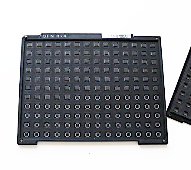
There is a tab on the top edge of the mini-tray. By convention, this holds some texts on the type, size and features of the tray. I only put the package style and body size on it (where QFP is generic for TQFP, LPQFP, VQFP and others). The rest of the tab is then available for a label with the manufacturer part number (or any other text of your choosing). The tab is suitable for 6 mm label tape.
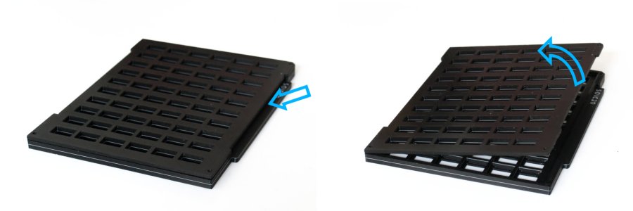
To remove the lid of a mini-tray, start at the tab, and lift that edge up first. The lid overhangs the mini-tray by 1 mm at the tab, so it is easy to get your finger under it.
The design of the mini-tray is in OpenSCAD. Via the OpenSCAD “Customizer”, you can select to print either the mini-tray, the matching lid, or both. The OpenSCAD source file has quite a few options. There are pre-configured settings for common packages, but you can also make a mini-tray for a custom packages. See also the section “Printing recommendations” for more information.
Files
All print files are in the 3MF format, as these are more compact than STL files and they also store configuration settings. Each file has a tray and its matching cover.
All print files can be generated from the OpenSCAD source file. The source file has a few more pre-set configurations, for the less common shapes.
| Description | File |
|---|---|
| OpenSCAD source files |  |
| (STL file) BGA 4.5×4.5 mm, 16 columns, 12 rows, 192 components | |
| (STL file) QFN 3×3 mm, 14 columns, 11 rows, 154 components | |
| (STL file) QFN 4×4 mm, 14 columns, 11 rows, 154 components | |
| (STL file) QFN 5×5 mm, 14 columns, 11 rows, 154 components | |
| (STL file) QFN 6×6 mm, 14 columns, 11 rows, 154 components | |
| (STL file) QFN 7×7 mm, 10 columns, 8 rows, 80 components | |
| (STL file) QFN 8×8 mm, 10 columns, 8 rows, 80 components | |
| (STL file) QFN 9×9 mm, 10 columns, 8 rows, 80 components | |
| (STL file) QFN 10×10 mm, 8 columns, 6 rows, 48 components | |
| (STL file) QFP 5×5 mm, 12 columns, 9 rows, 108 components | |
| (STL file) QFP 7×7 mm, 10 columns, 8 rows, 80 components | |
| (STL file) QFP 10×10 mm, 8 columns, 6 rows, 48 components | |
| (STL file) QFP 12×12 mm, 7 columns, 5 rows, 35 components | |
| (STL file) QFP 14×14 mm, 6 columns, 4 rows, 24 components | |
| (STL file) QFP 14×20 mm, 6 columns, 4 rows, 24 components | |
| (STL file) QFP 20×20 mm, 5 columns, 4 rows, 20 components | |
| (STL file) QFP 24×24 mm, 4 columns, 3 rows, 12 components | |
| (STL file) QFP 28×28 mm, 4 columns, 3 rows, 12 components | |
| (STL file) QFP 32×32 mm, 3 columns, 2 rows, 6 components | |
| (STL file) QFP 40×40 mm, 2 columns, 2 rows, 4 components | |
| (STL file) SO6L-4, 10 columns, 12 rows, 120 components | |
| (STL file) SOIC16W, 10 columns, 7 rows, 70 components | |
| (STL file) SOIC20, 10 columns, 6 rows, 60 components | |
| (STL file) SOT223, 12 columns, 9 rows, 108 components | |
| (STL file) SPDIP4L, 10 columns, 8 rows, 80 components | |
| (STL file) sTSOP32 11.8×8 mm, 13 columns, 5 rows, 65 components | |
| (STL file) sTSOP32 18×8 mm, 13 columns, 4 rows, 52 components | |
Printing recommendations
An ESD-safe plastic is highly recommended. These plastics may also be called anti-static, dissipative or conductive.
There are four holes in the corners of the mini-tray. These holes are specified in the design as 2.1 mm diameter. Due to the nature of 3D printing, they will typically come out a little smaller; the holes are intended for magnets of ⌀2×5 mm (⌀2×2 mm magnets in the lid).
The text on the tab is “engraved”, so to speak: the top layer of the tab has the text cut out. We often mark a filament switch just before the last full layer of the tab, and another filament switch just after it. It allows us to add a single layer of another colour (e.g. white), to enhance the contrast of the engraved text.
Limitations
You cannot use an automatic JEDEC tray exchanger on mini-trays. Automatic tray exchange (“unstacking”) was not a design goal for the mini-trays. Then again, if you have a pick-&-place machine with an automatic tray lift, you probably don't need mini-trays.
With regards to baking, only polycarbonate (PC) has a sufficient heat deflection temperature to create a “high-temperature” carrier, suitable for baking at 125 °C. 3D printed mini-trays from PETG, ABS and (especially) PLA must be considered “low-temperature carriers” (for use in drying cabinets with a baking temperature of 40 °C).
Changes from the earlier release
This is our second design for the mini-tray. The first design was a stackable mini-tray, to copy the stackable property of standard JEDEC trays. However, for a mini-tray, that property is rather useless. In relation to 3D printing, the drawback of making the mini-tray stackable is that you will either need to print the tray in two parts (which are then glued together), or print with supports (which you will then have to remove after printing).
The OpenSCAD source file still has an option to create a stackable mini-tray, but the ready-to-print 3MF files are all for non-stacking trays.
The previous release for the mini-tray used a relatively fine honeycomb grid for the lid (and for the bottom of the trays). The idea was to make the lid universal: a single lid design to cover every tray, regardless of whatever component the tray holds. We abandoned this because the fine grid made it hard to check on the number of components in the tray with the lid still on. In addition, a tray and its lid form a pair: in practice, we would never print a tray without lid. The important bit is that a tray has a lid, and whether that is a dedicate lid or a universal one, doesn't matter much. The drawback of the universal lid outweighed its advantage.
Finally, the tab is now aligned to the bottom, instead of to the top as in the previous release. This is mainly for ease of printing. More importantly, it is now 3 mm thick, 1 mm thicker than before. (If you set the “stackable” option to true, the tab will be aligned to the top, as it was previously.)
See also
We also made a design for a smaller version of the standard reel: the mini-reel. This smaller version of the common 7" reel takes less space on the shelves, and offers a few other features.
