

VisualPlace
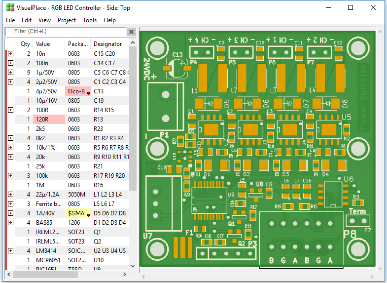
Screen-shot of the VisualPlace program
VisualPlace is a software tool for and managing and visualizing the ‘production files’ for PCB assembly (printed circuit board). Intended use of VisualPlace is during assembly of the board (either by hand or automated), as well as during inspection and trouble-shooting. VisualPlace has a plug-in architecture for reading the data files, so that it can easily be adapted to various ‘electronic design automation’ (EDA) suites.
When used with a camera, VisualPlace functions as a digital magnifier as well. The component locations are overlaid onto the live camera image.
If the production files with the placement positions are unavailable, VisualPlace can help you create them. VisualPlace scans the PCB images (notably the silk-screen) and uses character and shape recognition techniques (OCR) to establish footprint positions and map these to the designators of the components.
Downloads, requirements & license

- VisualPlace 4.1, build 7662 Setup (6.4 MiB)
- The VisualPlace application and all associated data files and plug-ins, as a self-extracting setup, for Microsoft Windows. This download is recommended for users of Microsoft Windows.
- VisualPlace 4.1, build 7662 without setup (7.9 MiB)
- The VisualPlace application and all associated data files and plug-ins, as a ZIP file. This download is recommended for Linux/Wine.
- Requirements
- VisualPlace runs under Microsoft Windows, starting from Microsoft Windows XP. It also runs under Linux with Wine (for context-sensitive help, you need Evince or Okular; other PDF readers lack the command line options that VisualPlace needs).
- License
- VisualPlace is copyrighted software that is free for personal and commercial use. You may use it and distribute it without fee. You may however not remove or conceal the copyright. There are no guarantees or warranties whatsoever; use it at your own risk. The full license is in the product manual, which is installed with the product.
- Recent changes
- Please see the Release notes.
Running under Linux
VisualPlace is a Windows application that runs under Linux thanks to
Wine. The first step in
setting up VisualPlace under Linux is therefore to install Wine through the
package manager. We recommend to download the ZIP archive of VisualPlace and
unpack it (the ZIP file has folders, this folder structure must be kep intact).
VisualPlace is indifferent where you install the program; it may be in your home
directory or in the ‘/opt’ directory (in the latter
case, you need to unpack the ZIP archive with sudo).
To launch VisualPlace, run visualplace in the bin
subdirectory of where VisualPlace is installed. This is an ELF program that
launches Wine and the VisualPlace main application.
As a side note, when VisualPlace runs under Wine, it translates all paths between the Windows syntax (used by Wine) and the Linux syntax (so that the user sees standard Linux paths). The file and folder selection dialogs in VisualPlace are the native GTK+ dialogs in Linux. To the user, it appears that VisualPlace uses the Linux file system. However, in the background, it is still emulated by Wine, and a notable difference is that the Wine file system is case-insensitive.
Usage
A detailed user manual is included in the ‘setup’ (see Downloads above). For a ‘walk-through’ introduction, please see the videos below.
Rationale
VisualPlace is designed with three goals:
- For PCB designers, to review and verify (and possibly correct) the production files before shipping them off to a PCB assembly facility.
- For engineers doing hand assembly for a prototype (or small series), to make the assembly process more efficient.
- For PCB assembly facilities, to verify and review the production files handed to them, and to prepare the programming of the pick & place machine off-line.
VisualPlace combines the production files generated by an EDA suite with the ‘silk-screen’ images (in Gerber file format). After reading all the data in, the program compares, adjusts and aligns the information; it creates search lists and group orders, and visualizes the resulting data set in various ways.
Unlike PCB production itself, where Gerber photo-plotter files and Excellon drill files are the de facto standard, no standard is predominant for the pick & place machines used in the assembly phase. Virtually all EDA software can generate a file with the positions and orientations of the components of a board, and virtually all pick & place machines have a computer interface, yet these rarely match. This leads to ‘requirements’ like converting and fine-tuning the incoming production files, or even partially or fully (re-)generating the placement data from scratch. It gets worse: all this time, the pick & place machine sits idle, and manual regeneration carries a risk for errors.
When prototypes or small series are made, it is regularly not cost-effective to program the pick & place machine for it —also due to the problems described above. The boards are then assembled by hand. However, the technician doing so basically has to work from an (enlarged) copy of the ‘silk-screen’ image to locate each component. As a result, a significant amount of time is spent in searching each component on the board. This is inefficient, and it is error prone, because the silk-screen image may be ambiguous.
VisualPlace was made to address these issues. While perhaps not a panacea, VisualPlace is an improvement over the current practices.
Benefits for the PCB designer
It is (unfortunately) not uncommon for a PCB assembly firm to ask the PCB designers for the silk-screen artwork and the bill of materials, and then proceed to build the component placement data from scratch —even though, as stated before, nearly every EDA suite can generate these files. One reason why PCB assembly firms disregard the ‘generated’ production files from the EDA suite is that these production files are often incomplete and inaccurate. Since it is unknown where the production file is accurate and where it is not, the assembly facility may prefer to ignore it altogether and rebuild it from scratch.
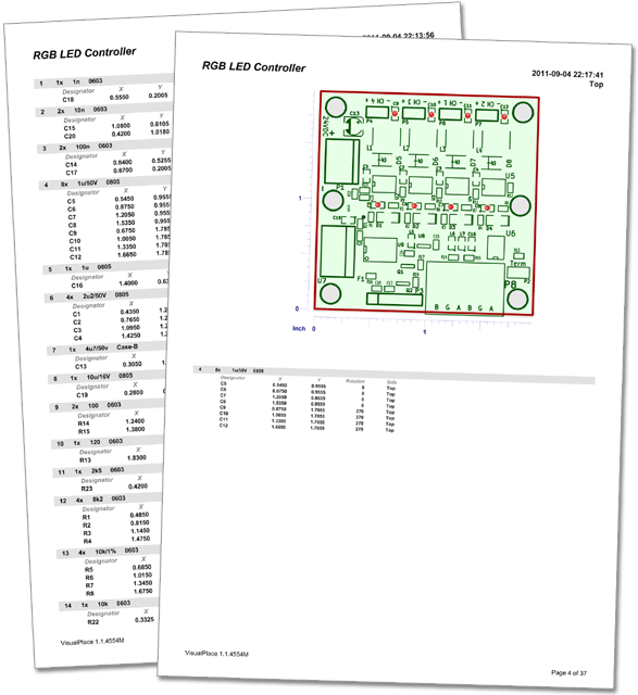
Reports generated from VisualPlace
That merits the question: why are production files from an EDA suite so often inaccurate (and incomplete)? In part, the answer is that the generation of production data is not a core feature of EDA suites —sometimes it is not even integrated, but provided as a ‘user script’. While generating the production files is still just a ‘click on the button’, the quality of those files dubious. EDA suites lack a program to let the designer verify the generated data, and therefore the PCB designer has no way to know what shape the placement data is in —letting errors in the data go undetected.
Now there is VisualPlace: VisualPlace reads the production files and the silk-screen Gerber, and lets the designer verify that the data is good. If the designer can tell the PCB assembly firm with confidence that the data is accurate, there is no more excuse for the assembly firm to waste time in rebuilding it from scratch. And if the assembly facility insists on having the data on paper, VisualPlace can generate these.
Benefits for automated PCB assembly
The bottleneck of the time required for data preparation and assembly recipe generation for a new PCB are well known. Sufficiently well known to gain a three-letter acronym: NPI, which stands for ‘New Product Introducion’. NPI causes machine down-time —and therefore increases costs.
Like the PCB designer, an engineer who needs to program the pick & place machine can run VisualPlace to verify the quality of the provided production files. If there are errors in the data, or if the data is incomplete, the engineer can take a note of these ‘exceptions’, or choose to correct them inside VisualPlace. There is no more need to throw the entire file away because there is (or may be) an error ‘somewhere’ in there.
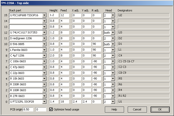
Preparing a project for the TM-220A or TM-240A table-top pick-&-place machine
A PCB assembly firm will receive production data in various formats —there is no standard file format, neither de facto nor formal, for the component placement. EDA suites use proprietary formats, which sometimes change between releases. Due to a plug-in architecture, VisualPlace detects and supports a variety of file formats for the production data, without needing manual intervention.
If the provided production files are unusable, VisualPlace can scan the designator labels on the PCB (the silk-screen) using OCR techniques, and match these to the bill of materials. In a second step, VisualPlace uses that information to identify footprint shapes and map the footprints to designators.
VisualPlace can also export the data, and again, it uses plug-ins to do so. If you have a suitable plug-in for your pick & place machine, you can prepare and optimize the data off-line, and then transfer the generated file directly to the machine. Even without a specific plug-in for your system, VisualPlace helps because its generic file formats are well documented and easy to parse by pick & place machines.
The first benefit for PCB assembly firms is reduction of work, because the component positions do not have to be (re-)generated from scratch: data preparation becomes data verification. The second benefit is that corrections in component placements that are specific to an EDA suite are automatically applied. Thirdly, the verification, correction and conversion of the production files occurs off-line. The pick & place machine can continue to run while a (next) project is being prepared, maximizing the machine utilization.
Benefits for manual PCB assembly
The quality of soldered connections depends predominantly on the dosing of the solder paste —position and amount. This is conveniently and accurately realized by using a stencil, but equally easily ruined when a component is not placed correctly on the board (and in the paste) in one go. When correcting the position of a component, you risk to smear the paste off the pads.
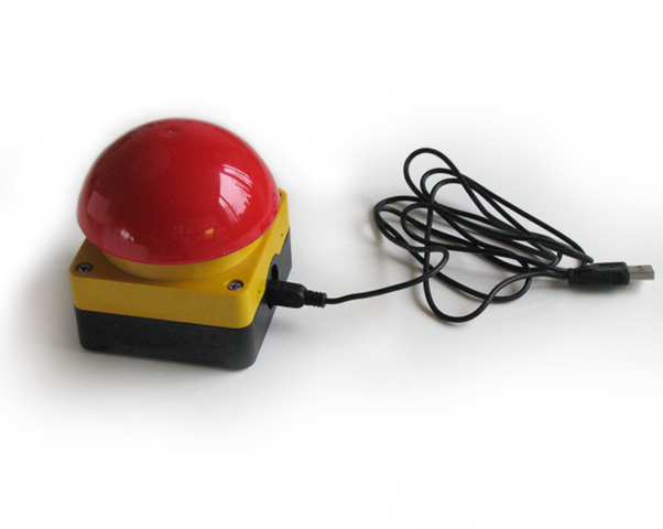
A foot/hand/palm switch, for use in manual assembly
Therefore, manual population of a PCB is a job that requires concentration —and a steady hand. Locating the next component to place, by skimming through the bill of materials and (enlarged) print-outs of the silk-screen images, then, is a ‘distraction’ to say the least. VisualPlace helps you during manual assembly of a board, by allowing you to walk through the bill of materials, read how many parts of a particular value and footprint are needed, and see in a glance where they are located on the PCB.
A small, but important, detail is that VisualPlace shows you the orientation of the component on a board, which is especially relevant for LEDs and diodes, because the silk-screen may be ambiguous on the required orientation.
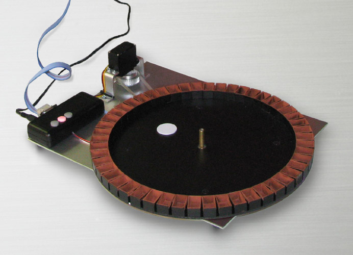
A component carousel for manual assembly
VisualPlace is designed to be operated with the keyboard and with a minimum number of key strokes —which can be emulated with large pushbuttons or a foot switch. It is also highly configurable in the visualization (sorting order, zoom, grouping, …) and the information on components that it shows at any time, depending on personal preferences or the requirements of the project at hand.
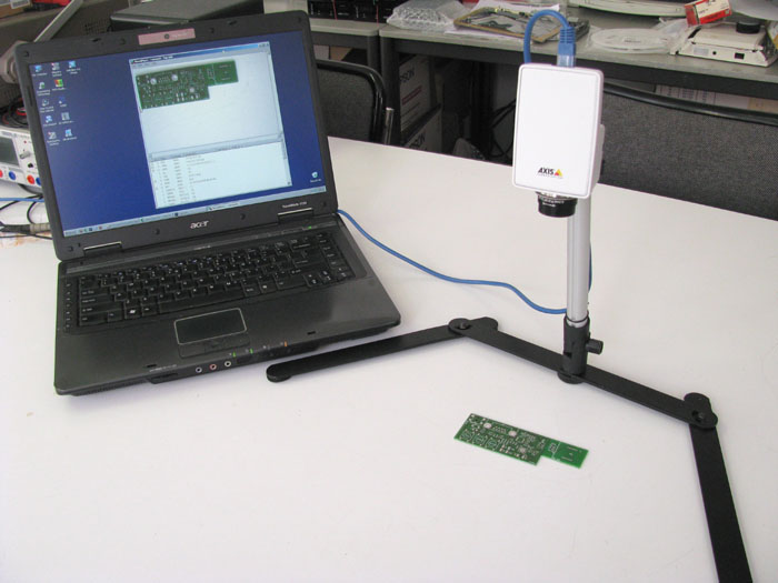
Camera magnifier
A plug-in system allows you to drive other equipment from VisualPlace. One example is a motorized component carousel, with exchangable disks. The carousel has its own software, but a plug-in for VisualPlace is available. With the plug-in, VisualPlace knows which disk is mounted in the carousel (because each disk has an RFID tag), and which components it holds (and in which bins). When you select a part in VisualPlace, you will see on the display where these components go on the PCB and the carousel turns the bin with the appropriate part to the pick-up position.
With camera support, VisualPlace functions as a digital magnifier for the PCB during assembly, as well as a component locator via its ‘markers’ that it overlays on the captured camera images. In this mode, VisualPlace displays a live view the actual PCB (instead of the design drawings / Gerber files), with the component locations as overlays.
VisualPlace and Gerber X2 & X3
The Gerber X2 standard is the latest evolution of the Gerber file format for PCB production. Gerber X2 adds file attributes and aperture attributes: auxiliary information that is useful to unambiguously specify the layer stack-up in multi-layer PCBs, and for distinguishing pads from traces, and determining which part a pad belong to.

VisualPlace uses the Gerber X2 attributes, if present, for the following:
- The automatic (and accurate) alignment of the component placement data (CPL file, XYRS file, centroid file, …) with the Gerber artwork.
- The matching of packages (from the bill-of-materials) to the footprints on the Gerber artwork, as well as suggesting an alternative package on a mismatch.
- The automatic correction of the position and/or the orientation of components (which is relevant because many component libraries for EDA suites specify the pick-up point for the component incorrectly or inaccurately, and the orientations may not adhere to the IPC-7351 and IEC 61188-7 standards).
- Highest accuracy in measurements of pad locations and pad distances, directly from the Gerber artwork.
As a result, we recommend that you switch over to Gerber X2 if your EDA suite supports it.
Gerber X3 is a new specification for addding component data to the PCB design files. VisualPlace is able to extract component positions and a bill-of-materials from it. Since the ‘X3’ files are generated along with the other Gerber files, these are guaranteed to be aligned. The Gerber X3 format is also one of the very few file formats for component placement data that has a formal written specification.
For these reasons, the Gerber X3 format is the preferred format for component data, if your EDA suite supports it.
Help requested
VisualPlace is used in production at several sites —it is fully functional and tested software. Regardless, improvements and extensions are certainly possible. It is our intent to improve VisualPlace over time, based on user input and contributions.
For all questions, suggestions and contributions, please use the e-mail address info@compuphase.com.
- If you find a bug, please report it.
- If you have tips or corrections for the documentation, please send them to us.
- If you have production files that VisualPlace does not support, please send them to us together with a Gerber for the silk-screen. We will use these files only for testing, but nevertheless, do not send us any confidential data. Please also indicate what EDA program and version were used to create the production files.
- Component placement data is not always accurate in the libraries provided with EDA suites. VisualPlace allows you to build correction tables for those libraries. If you have created a set of placement corrections for your EDA suite in VisualPlace, you can send us your ‘user.ini’ file (which contains these corrections). This file is found either in the ‘data’ directory below the directory where VisualPlace is installed, or in ‘C:\Documents and Settings\<user>\Application Data\VisualPlace’. Note that by sending us this data, you license us to use the information in future versions of VisualPlace.
- If you wish to translate VisualPlace (or correct translations), first get the document ‘How to translate VisualPlace’. You can send the translated files to us. Note that by sending us your translations, you license us to include them in future versions of VisualPlace.
Auxiliary programs and alternatives
- PCBSynergy
- PCBSynergy is a utility that can generate the assembly programs for more
than 60 pick-&-place machines. Additionally, the program generates a
bill-of-materials and allows you to configure the feeder list.
PCBSynergy can be started from VisualPlace via the ‘export’ plug-in (PCBSynergy must be installed separately; the VisualPlace set-up only contains the plug-in, not the program).
